ASSEMBLY
OM 0313QH-A
18
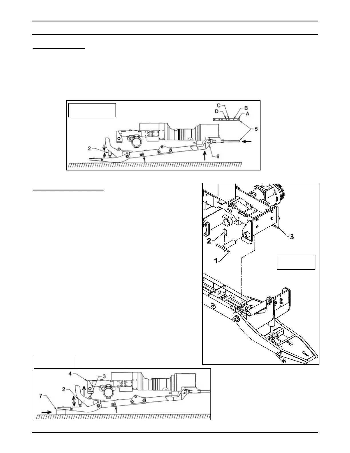
Figure 9b
Step 2: (Figure 8)
• Sit on the operator"s seat, start the engine
and slowly compress the cylinder (item 2)
using the hydraulic valve lever. This
operation will raise the subframe (item 6).
• Make sure that the rear of the subframe
(item 6) is well aligned with the tractor draw
bar (item 5) and shut off the engine. Insert
the draw bar between the two pins on the
rear subframe (item 6) and secure the draw
bar (item 5) to the tractor in position "D".
Step 3: (Figure 9a & 9b)
• Using a lever arm (not included), raise the
male quick hitch nose and insert a 3" thick
wood block (item 7, not included) under the
quick hitch nose.
• Sit on the operator's seat, start the engine
and slowly extend the cylinder (item 2)
using the hydraulic valve lever, until the
front subframe tube (item 3) is pressed
against the inside of the front bracket (item
4) bent plate. The front bracket tubes (items
4) will then be aligned with the front
subframe tube (item 3). Shut off the engine
and insert the two 1 3/4" "T" pins (Fig.9b,
item 1) in the front bracket (Fig.9b, item 3)
and secure with the two 3/8" x 2 1/2" pipe
pins (Fig.9b, item 2).
Figure 8
Figure 9a
 Loading...


