ASSEMBLY
OM 0313QH-A
19
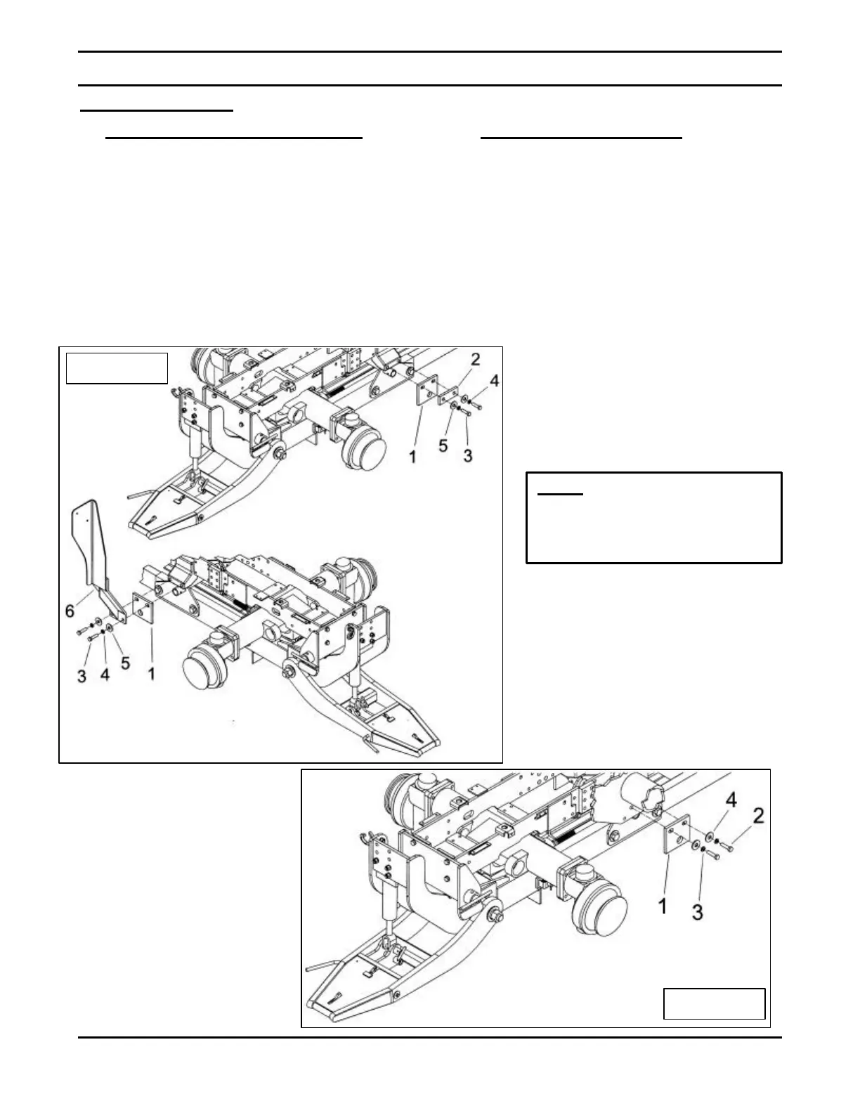
Figure 10a
Étape 4: (Figure 10a)
• If you do not own the front loader, Place
the mid support installation plates (item 1),
the spacer (item 2) and the valve support
(item 6) as shown on figure 10a and attach
to each side of the tractor using M16 x 1.5 x
55mm lg hex. bolts (item 3), 16mm
lockwashers (item 4) and Ø 11/16" int.
flatwashers (item 5). For now do not
tighten the M16 x 1.5 x 55mm lg hex bolts
(item 3).
• If you own the front loader, Place the mid
support installation plates (item 1) as
shown on figure 10b and attach to each
side of the tractor using M16 x 1.5 x 55mm
lg hex. bolts (item 2), 16mm lockwashers
(item 3) and Ø 11/16" int. flatwashers(item
4). For now do not tighten the M16 x 1.5 x
55mm lg hex bolts (item 2).
Figure 10b
of the installation plates
10a and 10b, item 1)
the rear of the tractor.
 Loading...


