ASSEMBLY
OM 0313QH-A
20
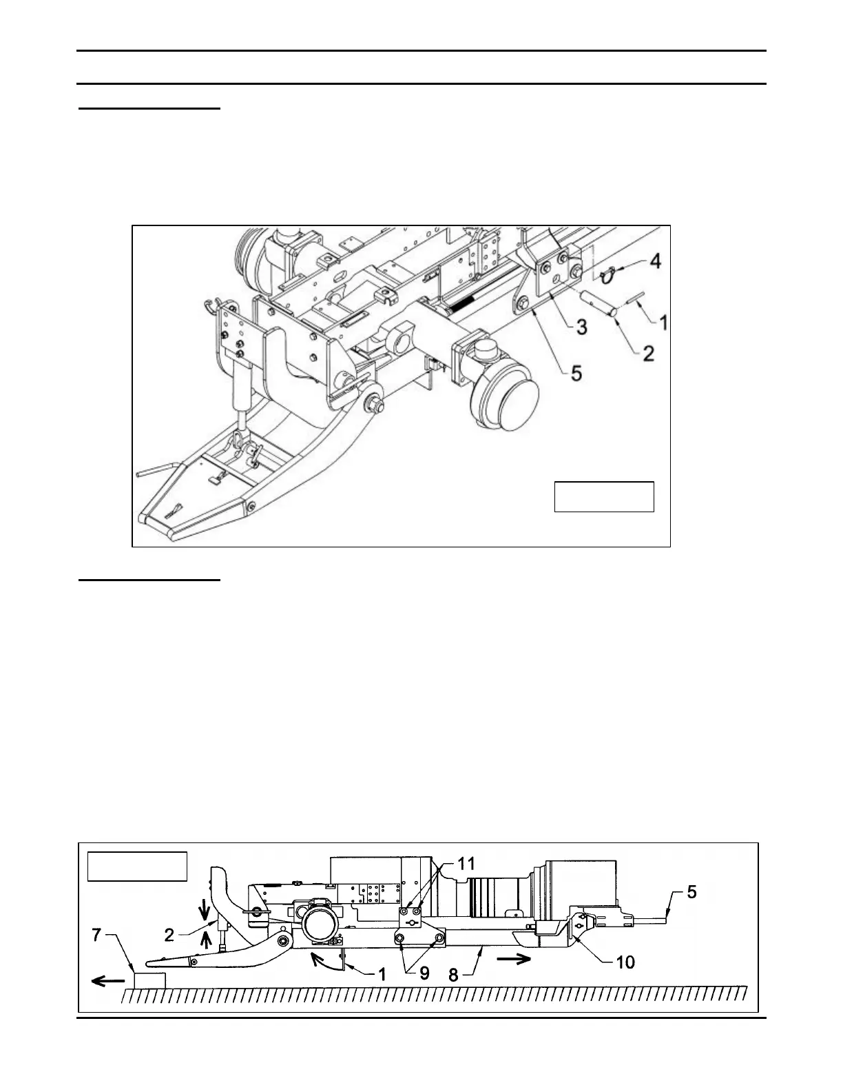
Étape 5: (Figure 11)
• Insert a Ø 5/16" x 3" lg pin (item 1) in the
hole located at the end of each Ø 1 1/4" x 5
3/4" lg pin (item 2).
• Then insert the Ø 1 1/4" x 5 3/4" lg pins
(item 2) in the hole of each mid support
installation plates (item 3) and in the mid
support tube (item 5) and fasten with the
two 1/4" round lock pins (item 4).
Étape 6: (Figure 12)
• Sit on the operator's seat, start the engine
and compress the cylinder (item 2) using
the hydraulic valve lever. Shut off the
engine and remove the wood block (item
7).
• Move the rear subframe (item 8) until the
plate (item 10) is perfectly pressed against
the tractor draw bar (item 5).
• Adjust and tighten securely the four 3/4"NC
x 2 3/4" bolts (item 9) to 297 lbs-ft or 403 N-
M and the four M16 x 1.5 x 55mm (item 11)
to 130 lbs-ft or 176 N-M.
• Lastly, pull on the subframe's parking stand
pin (Fig. 3, item 26) and push the parking
stand (item 1) towards the front until the pin
lodges into the second hole.
Figure 11
Figure 12
 Loading...


