ENGINE
B2050, B2350, B2650, B3150, WSM
1-S43
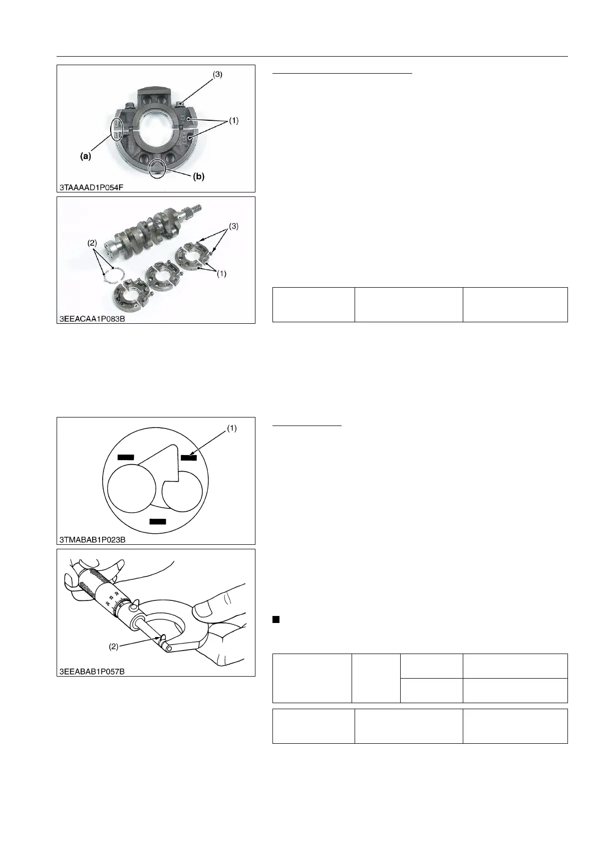
Main Bearing Case Assembly
1. Remove the two main bearing case screws 1 (3) of each main
bearing cases.
2. Remove the main bearing case from crankshaft.
(When reassembling)
• Clean the oil passage in the main bearing cases.
• Apply clean engine oil on the bearings.
• Install the main bearing case assemblies in original positions.
Since diameters of main bearing cases vary, install them in
order to marking (b) (A, B, C) from the gear case side.
• Match the alignment numbers (a) on the main bearing case
assembly 1.
• When installing the main bearing case 1 and 2, face the mark
"FLYWHEEL" to the flywheel.
• Install the thrust bearing (2) with its oil groove facing outward.
• Make sure that the main bearing case moves smoothly after
tightening the main bearing case screw 1 to the specified
torque.
9Y1210982ENS0074US0
[4] SERVICING
(1) Cylinder Head and Valves
Top Clearance
1. Remove the cylinder head. (Do not try to remove the cylinder
head gasket.)
2. Move the piston up and stick a strip of fuse [1.5 mm dia.
(0.059 in. dia.), 5.0 to 7.0 mm long (0.20 to 0.27 in. long)] on the
piston head at three positions with grease so as to avoid the
intake valve and the exhaust valve and the combustion
chamber ports.
3. Lower the piston, and install the cylinder head and tighten the
cylinder head screws to the specified torque.
4. Turn the flywheel until the piston exceeds top dead center.
5. Remove the cylinder head, and measure the thickness of the
squeezed fuses.
6. If the measurement is not within the factory specifications,
check the oil clearance between the crankpin and the crankpin
bearing and between the piston pin and the small end bushing.
• After checking the top clearance, be sure to assemble the
cylinder head with a new cylinder head gasket.
9Y1210982ENS0075US0
Tightening torque Main bearing case screw 1
30 to 34 N·m
3.0 to 3.5 kgf·m
22 to 25 lbf·ft
(1) Main Bearing Case Assembly 1
(2) Thrust Bearing
(3) Main Bearing Case Screw 1
(a) Alignment Number
(b) Marking (A, B, C)
Top clearance
Factory
specifica-
tion
D1105, V1505
0.55 to 0.75 mm
0.022 to 0.029 in.
D1305
0.80 to 1.0 mm
0.032 to 0.039 in.
Tightening torque Cylinder head screws
64 to 68 N·m
6.5 to 7.0 kgf·m
47 to 50 lbf·ft
(1) Fuse (2) Fuse
 Loading...

