ELECTRICAL SYSTEM
L3560, L4060, L4760, L5060, L5460, L6060, WSM
9-S68
(7) Glow Control System
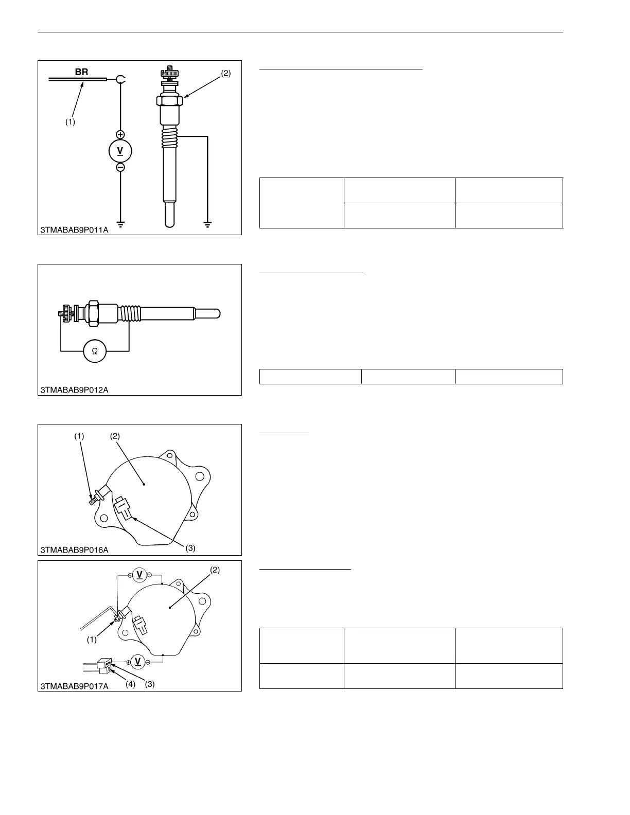
Glow Plug Lead Terminal Voltage
1. Disconnect the wiring lead (1) from the glow plug (2) after
turning the main switch off.
2. Turn the main switch key to the "PREHEAT" position, and
measure the voltage between the lead terminal and the chassis.
3. Turn the main switch key to the "START" position, and
measure the voltage between the lead terminal and the chassis.
4. If the voltage at either position differs from the battery voltage,
the wiring harness or main switch is faulty.
9Y1210824ELS0079US0
Glow Plug Continuity
1. Disconnect the lead from the glow plugs.
2. Measure the resistance between the glow plug terminal and the
chassis.
3. If 0 ohm is indicated, the screw at the tip of the glow plug and
the housing are short-circuited.
4. If the factory specification is not indicated, the glow plug is
faulty.
9Y1210824ELS0080US0
[7] CHARGING SYSTEM
Alternator
1. Disconnect the 2P connector (3) from alternator after turning the
main switch "OFF".
2. Perform the following checkings.
9Y1210824ELS0081US0
Connector Voltage
1. Turn the main switch "OFF". Measure the voltage between the
B terminal (1) and the chassis.
2. Turn the main switch "ON". Measure the voltage between the
IG terminal (3) and the chassis.
9Y1210824ELS0082US0
Voltage
(Lead terminal –
Chassis
Main switch key at
"PREHEAT"
Approx. battery voltage
Main switch key at
"START"
Approx. battery voltage
(1) Wiring Lead (Positive) (2) Glow Plug
Glow plug resistance Factory specification Approx. 0.9 Ω
(1) B Terminal
(2) Alternator
(3) 2P Connector
Voltage
(Main switch at
OFF)
B terminal – Chassis Approx. battery voltage
Voltage
(Main switch at ON)
IG terminal – Chassis Approx. battery voltage
(1) B Terminal
(2) Alternator
(3) IG Terminal
(4) L Terminal
 Loading...


