FNL
16 / 31
3.6 Connect Service Interface
RS232 Service Interface
To configure the FNL, terminals can be connected via the terminal
connection (RS232/V24). In general, the terminal consists of a PC
with corresponding terminal emulation. We recommend hyper
terminal under Windows XX. What can be controlled or observed via
the terminal is described in the section „Setting into Operation“.
Clamps 5 … 8 serve as terminal connection and as 24 V output for
the internal PA power supply.
Clamp Voltage Usage
5 24V supplies the 24 V that are needed to activate
the internal PA power supply (only available
with the PA Version of FNL) .
6 0V is the 0 V for the RS232 interface.
7 V24 level is the outgoing data line of the RS232 interface
from viewpoint of the FNL.
8 V24 level is the incoming data line of the RS232 interface
from viewpoint of the FNL.
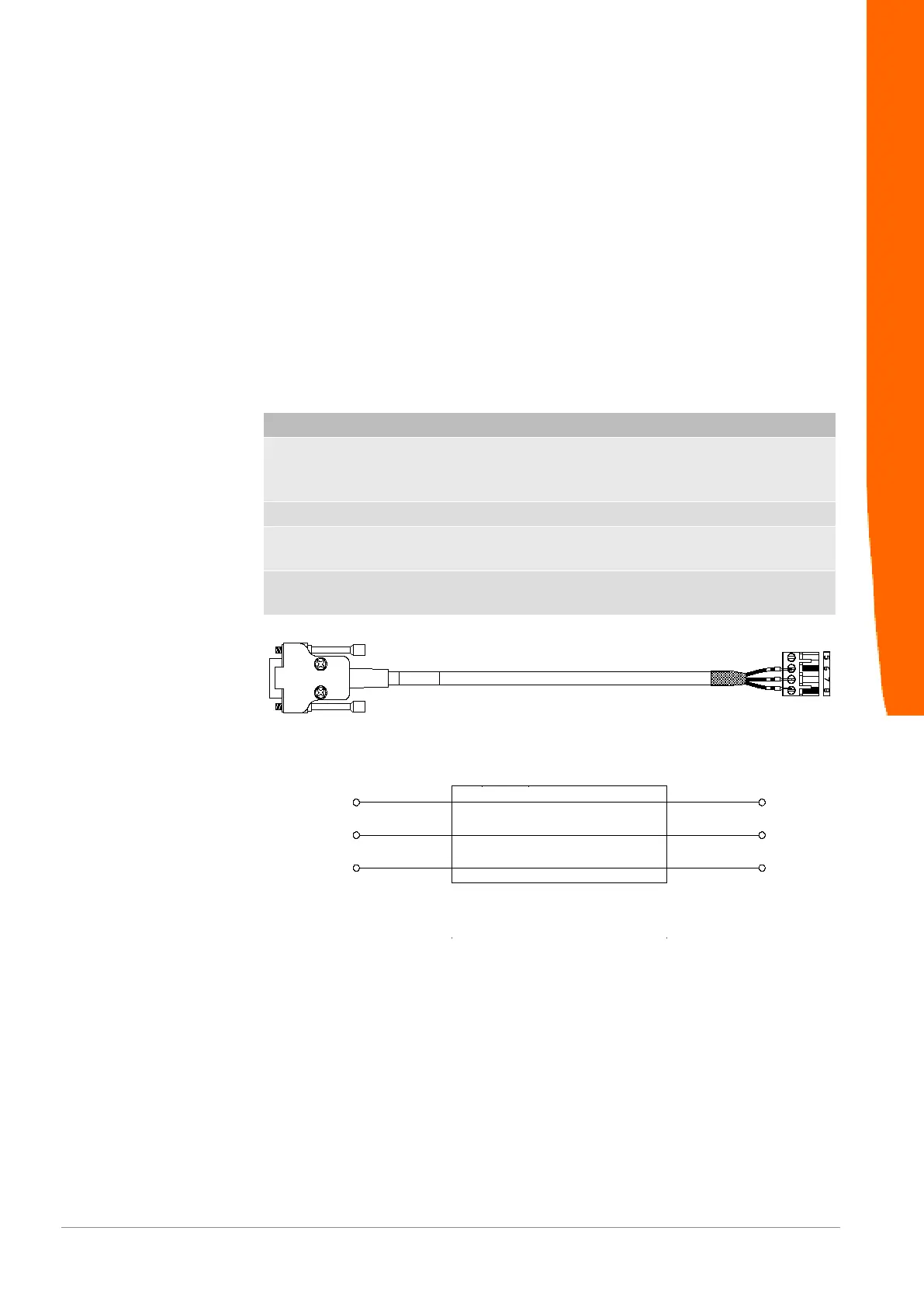
Pin assignment RS232-
Interface cable
5 6
7
GND
GND
T x D2
Rx D
D S U B 9 f e m a l e
8 Rx D3
T x D
b r
ws
g e
b r
ws
g e
Illustration6: RS232 cable
Install
 Loading...