Do you have a question about the KUNTENG KT-LCD10YN and is the answer not in the manual?
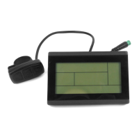
Provides the physical dimensions of the electric bicycle meter.
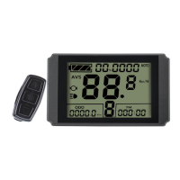
Details the dimensions for mounting the meter using a dual bracket.
Specifies the primary materials and color of the meter housing.
Details the display of single and total trip time (TIM, TTM) and distance (DST, ODO).
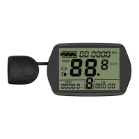
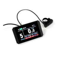
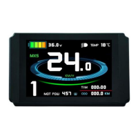
Explains the display of real-time speed, maximum speed (MXS), and average speed (AVS).
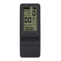
Shows indicators for handlebar status and power-assist startup.
Details power assist ratio switching and the 6Km/H push assist function.
Describes the activation and use of the cruise control function.
Explains battery capacity, real-time voltage, and voltage compatibility.
Details the display of motor power and operating temperature.
Covers brake, backlight, environment temperature, data clearing, and fault code displays.
Guides on accessing and modifying user-configurable parameters.
Instructions on how to power the meter on and off, including auto-shutdown.
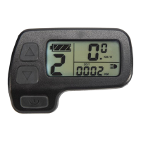
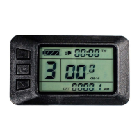
Overview of the different display modes and how to navigate them.
Shows how the meter indicates the remaining battery charge.
Details the display of the single trip time (TM).
Explains the display of the current power assist level or gear.
Shows the current riding speed in Km/H.
Details the display of the single trip distance (DST).
Illustrates the display for the 6Km/H push assist function.
Shows the display for the motor's current operating power.
Displays the ambient environmental temperature.
Indicates the status of the meter's backlights and vehicle headlights.
Shows when the brake status is active.
Illustrates the display for the activated cruise control function.
Displays the current operating temperature of the motor.
Shows the maximum speed (MXS) achieved during the trip.
Explains the display of the real-time battery voltage (VOL).
Explains the visual representation of fault codes on the meter.
Allows configuration of general project-wide parameters.
Enables setting of parameters related to motor characteristics and control.
Allows configuration of controller-related parameters.
Enables setting of parameters related to under-voltage control.
Setting motor characteristic parameters based on gear ratio and magnet pieces.
Configuring the number of wheel speed pulses per revolution.
Setting the power assist control mode (imitation torque or speed control).
Configuring the handlebar startup mode ('non-zero' or 'zero' startup).
Setting the power monitoring mode (real-time voltage or smart power).
Selecting power-assist sensor type and parameters.
Setting motor phase classification for sine wave drive.
Initializing the power assist ratio gear.
Configuring handlebar functions and speed limits.
Adjusting the controller's maximum operating current limit.
Adjusting the brightness level of the meter's backlight.
Configuring whether the cruise function is enabled or disabled.
Configuring whether the motor operating temperature is displayed.
Enabling or disabling the power-on password function.
Configuring automatic restoration of factory default settings.
Selecting meter attributes, such as communication protocol compatibility.
Adjusting the controller's minimum operating voltage for shortage detection.
Setting ABS braking strength and energy recovery efficiency parameters.
Setting parameters for power-assist tuning based on motor type and P3 setting.
Setting the speed limit for the push-assist function.
Setting under-voltage values for automatic under-voltage controllers.
Parameters for super high-speed motor controllers, related to P1.
Settings for dual mode controllers, related to Hall sensor failure.
Diagram illustrating the wiring for meter parameter copying.
Details the special wiring cables needed for parameter copying.
Shows the display interface after successful parameter copying.
| Brand | KUNTENG |
|---|---|
| Model | KT-LCD10YN |
| Category | Bicycle Accessories |
| Language | English |