Do you have a question about the KUNTENG KT-LCD11 and is the answer not in the manual?
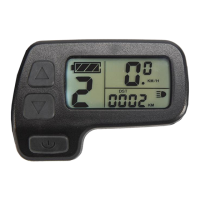
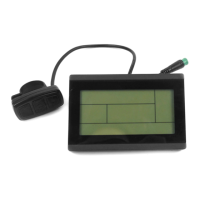
Displays the physical dimensions of the KT-LCD11 meter.
Describes the material (PC) and color (black) of the meter housing.
Provides a diagram illustrating the wiring connections for the meter.
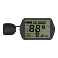
Shows a visual representation of the meter's physical installation on handlebars.
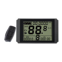
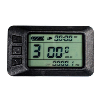
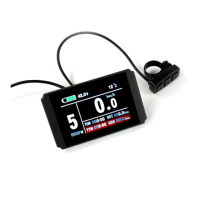
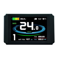
Details the display of real-time speed (KM/H, MPH) and trip/total distance (DST, ODO).
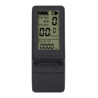
Identifies various indicators and data points shown on the meter display.
Explains how to power the meter on and off using the SW button.
Illustrates various modes displayed in Display 1, like battery, PAS, speed, and distance.
Shows display indicators for brake status and cruise function.
Illustrates displays for power-assist startup and throttle activation.
Explains the display of Total Trip Distance (ODO) in Display 2.
Details the display of Single Maximum Speed (MXS).
Explains the display of real-time battery voltage (VOL).
Shows how the display indicates the throttle is activated.
Describes the flashing PAS sign indicating power-assist startup.
Explains how to switch power assist levels (0-5) using UP/DOWN buttons.
Details the 6KM/H power assist function for pushing the bike.
Explains how to activate and revoke the cruise control function.
Describes how to turn on/off meter backlighting and vehicle headlights.
Explains how battery capacity is displayed and voltage shortage indicators.
Details the procedure to clear single trip distance (DST) data.
Outlines the main categories for parameter configuration.
Describes how to set the maximum allowed riding speed.
Explains how to select the correct wheel diameter for accurate speed readings.
Details how to switch between metric (Km/h) and imperial (MPH) units.
Explains setting the motor gear reduction ratio and magnet poles.
Details setting the number of pulses per wheel revolution.
Explains selecting between torque control and speed control modes.
Configures throttle behavior: non-zero or zero startup.
Sets up battery capacity monitoring based on voltage or smart power.
Configures the power assist sensor type and sensitivity.
Sets motor phase identification for sine wave drive.
Initializes the power assist ratio gears and default settings.
Configures various throttle behaviors and speed limits.
Adjusts the controller's maximum operating current limit.
Adjusts the brightness level of the meter's backlight.
Enables or disables the cruise control function.
Parameter C8 is not identified or used in this version.
Sets up a password to prevent unauthorized startup.
Configures whether the meter automatically restores factory settings.
Selects meter attributes for communication protocol compatibility.
Adjusts the minimum operating voltage threshold for the controller.
Configures ABS braking strength and energy recovery efficiency.
Adjusts the strength and type of power assist.
Sets the speed limit for the push-assist function.
Configures under-voltage protection for automatic under-voltage controllers.
Configures parameters for super high-speed motor controllers, linked to P1.
Configures dual-mode controller operation (Non-Hall or optimized model).
Illustrates the wiring diagram for copying meter parameters.
Describes the special cable and procedure for parameter copying.
| Voltage | 24V/36V/48V |
|---|---|
| Handlebar Size for Holding | 22.2 mm |
| Display Type | LCD |
| Waterproof Rating | IP65 |
| Compatible Controllers | Kunteng controllers |
| Functions | Speed, battery level, PAS level, error codes, trip distance, odometer |
| Connector Type | 5-pin waterproof connector |