Do you have a question about the KUNTENG KT-LCD8HP and is the answer not in the manual?
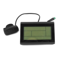
Displays the physical dimensions of the meter unit, including length, width, and depth.
Details the dimensions for mounting the meter using a dual bracket system on handlebars.
Provides the physical dimensions for the meter's button control box.
Illustrates how to install the meter on handlebars with a 31.8mm diameter.
Illustrates how to install the meter on handlebars with a 22.2mm diameter.
Shows a visual example of the meter physically mounted on an electric bike.
Details the display of single trip time (TM) and total trip time (TTM).
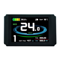
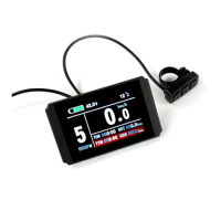
Covers real-time speed, maximum speed (MXS), and average speed (AVS) displays.
Explains the display of single trip distance (DST) and total trip distance (ODO).
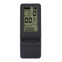
Shows how the display indicates when the throttle is activated.
Illustrates the display when the Pedal Assist System (PAS) is active.
Explains how to switch between power assist levels or throttle gears.
Describes the 6KM/H power assist function for pushing the bike.
Details the operation and display of the cruise control feature.
Explains the visual representation of the remaining battery power.
Shows the current voltage of the battery.
Displays the motor's real-time power output and operating temperature.
Indicates when the brake system is activated.
Explains how to turn on the meter's backlight and bike headlights.
Shows the ambient temperature in Celsius or Fahrenheit.
Describes the process for clearing trip data.
Explains how error codes are displayed when issues occur.
Covers how users can adjust various parameters for customization.
Notes the meter's automatic identification and compatibility with 24V, 36V, and 48V systems.
Illustrates the physical layout of the button box and its operating keys.
Details how to power the meter on and off, including automatic shutdown.
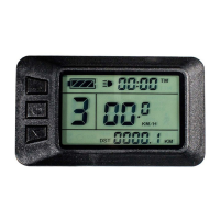
Explains the initial display screen (Display 1) upon powering on the meter.
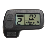
Describes the second display interface and its automatic transition.
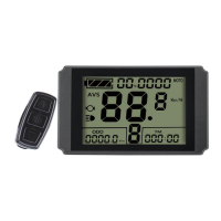
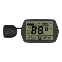
Explains how to access and navigate to Display 3 and subsequent displays.
Shows how the meter indicates when the throttle is engaged.
Illustrates the display when the Pedal Assist System (PAS) is active.
Explains how to change power assist levels (gears) using buttons.
Details the operation of the 6KM/H push assist feature.
Explains how to activate and deactivate the cruise control feature.
Describes how to turn on the meter's backlight and vehicle headlights.
Shows how the display indicates when the brakes are applied.
Explains the visual representation of the battery's charge level.
Provides details on how the battery capacity indicator functions and displays charge.
Explains how to view the motor's real-time power and temperature.
Describes the display of the ambient temperature.
Details the procedure to clear single trip time and distance data.
Explains the automatic prompt interface behavior.
Describes how to interpret error codes displayed on the meter.
Covers the initial setup and general project parameters.
Details the settings related to motor characteristics and performance.
Explains the configuration of controller parameters and system settings.
Covers settings related to under-voltage protection and motor controller types.
Sets motor gear reduction ratio and magnet pieces for performance calibration.
Configures the number of pulses per wheel revolution for speed measurement.
Selects the power assist control mode (imitation torque or speed control).
Configures throttle response: zero or non-zero startup.
Sets the power monitoring mode: real-time voltage or smart power.
Selects power assist sensor type and related parameters.
Sets motor phase classification for sine wave drive identification.
Initializes the power assist ratio gears upon meter startup.
Configures various throttle functions, including startup modes and speed limits.
Adjusts the controller's maximum operating current and startup levels.
Sets the brightness level for the meter's display backlight.
Enables or disables the cruise control function.
Configures whether to display the motor's operating temperature.
Enables and sets a password for meter startup.
Configures whether the meter automatically restores factory settings on reset.
Selects the meter's communication protocol version or data source mode.
Adjusts the minimum operating voltage for controller protection against low voltage.
Configures ABS braking strength and energy recovery efficiency.
Adjusts the assist strength for different pedal assist gears.
Sets the maximum speed for the push-assist function.
Configures automatic under-voltage selection based on battery voltage.
Adjusts P1 parameter behavior for super high-speed motor controllers.
Selects the operating model for dual-mode controllers based on Hall sensor status.
Adjusts the delay time for automatic LCD shutdown.
Illustrates the wiring connections required for parameter copying.
Details the specific wiring cable needed for the parameter copy function.
Shows the display interface after a successful parameter copy operation.
Highlights specific parameters (C9, C11) that cannot be copied.
Specifies that parameter copying is only supported between identical meter models.
Explains how to restore default factory settings using the C10 option.
Advises on parameter settings for torque controllers based on testing results.
Displays the software version of the KT-LCD8H P meter.
Indicates the release date of the manual or software version.
| Brand | KUNTENG |
|---|---|
| Model | KT-LCD8HP |
| Category | Bicycle Accessories |
| Language | English |