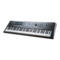
Interface PCB
Function Summary
The CUP2 Interface PCB performs the following functions:
1. ScanPort interface to 12 control panel LEDs and 14x5 dot matrix display.
2. ScanPort interface to 12 control panel buttons
3. ScanPort interface to the keyboard
4. MIDI In/Out connector interface to logic level signals
5. AC power entry socket and power line voltage selector
6. USB connector interface
7. Switch Pedal interface
8. ScanPort interface to volume control
9. Audio differential ampliers for audio signal from the Engine PCB
10. Speaker mute relay
11. ScanPort analog multiplexor
The following function summary descriptions reference the CUP2 Interface PCB, Rev C Ver 1,
schematic circuit drawings (Chapter 7, pages 7-8 and 7-9).
In the CUP2, the main CPU on the Engine PCB also performs scanning of the keyboard, LEDs,
and controls. This is done through the ScanPort connector, a simple, Kurzweil standardized,
CPU independent interface for scanning. Most of the subsystems on the Interface PCB connect
to the ScanPort.
ScanPort interface to control panel LED indicators and display
(page 1, zone C4)
The LED indicators and LED dot matrix display, located on the Control Panel PCB, are
connected into a 14 column by 8 row matrix. The column select shift register is actually on the
Control Panel PCB (see next page). The shift register drives the next column each time the
ScanPort writes new data into the LED row register (U2). A new scan begins when the ScanPort
RES signal is low during a row register write cycle. Scan rate is approximately 100Hz (10mS).
Printed Circuit Boards
Interface PCB
2-5
 Loading...