C
APPENDIX
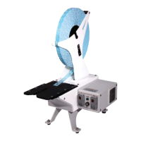
B. REMOVE THE TRIMMER GUARD:
(Figure A.5 & A.6)
1. Loosen the two guard mounting screws located
on the side of the trimmer assembly.
2. Use the end of a pencil to push the front of the
carriage backward away from the front of the
closer and lift the trimmer cover off. This
exposes the trimmer shear blade (Figure A.6).
CAUTION: THE SHEAR BLADE IS MADE OF A
CERAMIC MATERIAL AND IS EXTREMELY SHARP.
EXTRA CARE SHOULD BE TAKEN TO ENSURE
THE SAFE HANDLING OF THIS BLADE.
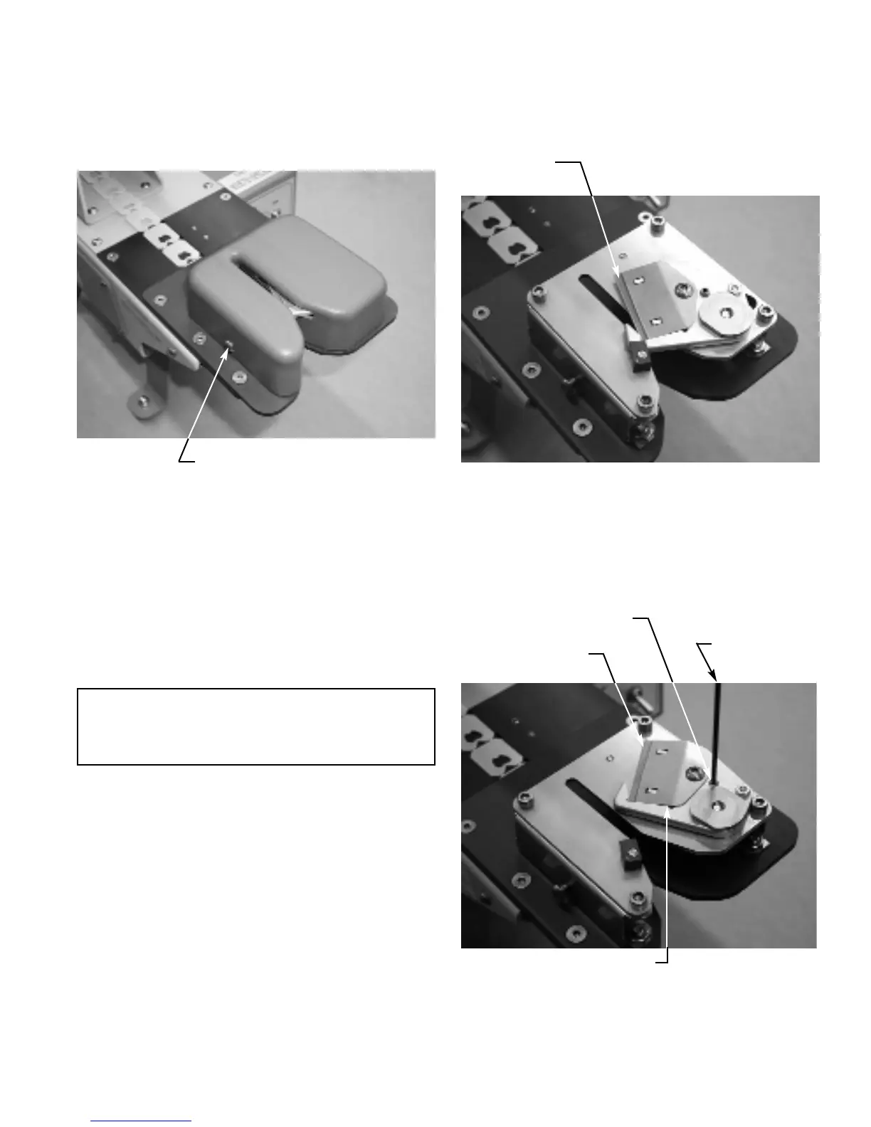
C. SHEAR BLADE “LOCKOUT”
The shear blade mechanism can be “locked out” of its
operating position. This is an option if the operator
wants to close a product without shearing off the top of
the bag.
1. Remove the trimmer guard as described in
“B” above.
2. Carefully swivel the blade assembly fully open
and turn the set screw into the carriage until it
is flush with the top of the hole (Figure A.7).
The blade assembly is now in the locked out
position.
3. Replace the guard and tighten the mounting
screws.
Figure A.5
Guard mounting screws (2)
Figure A.6
(cover removed)
Shear blade in
operating position
Figure A.7
Shear blade in
“lockout” position
Lockout set screw
Allen wrench
Blade retainer
086 A 10 00