Note)When current is flowing from the upside to the underside of the instrument, reading is
positive(+), on the contrary, reading to be negative(-) when current is flowing from the
undersidetotheupsideoftheinstrument.
6-1-2ACcurrentmeasurement
(1)Setthefunctionselectorswitchto"
〜
A"position.
("
〜
"and"A"markswillbedisplayedontheLCD.)
(2)Place one measured conductor lower than the triangle mark indicated on the fork shaped
sensorandmakeameasurement.(shadedpartinthefigure)
ThenmeasuredvalueisdisplayedontheLCD.
(Whenthecenterof theconductor isnot lowerthan thetriangle markindicated onthe fork
shapedsensor,erroroccurs.)
Note)For the measurement of AC current, zero adjustment, which is required for the
measurementofDCcurrent,isnotnecessary.Current flowingdirectionhasnorelationto
theindicationpolarity.
6-2Noncontactvoltagedetection(NCV)
This function is to check the presence of voltage without touchingwiresor electrodes
directly.
AlsocancheckthepresenceofACvoltageincable,outlet,fuseandcircuitbreaker.
[Details]
While voltage isapplied to a cable oroutlet,the electric field depending onthe voltage is
generated. Thisinstrument detectsthe generated electricfield, andverifies the presenceof
ACvoltage.Officially,itiscalledasaninstrumentfordetectingelectricalfield.Butitisnota
familiar term, so we call it as "Non contact voltage detection". General detectors detect
voltage by contacting polarized voltage(contacts and terminals). But this instrument is
developedtosatisfythisfunctionandforsafetypurposewithoutcontactingvoltage.
#
DANGER
●
To avoid gettingan electrical shock, never make measurementon the circuit in which
electricalpotentialoverAC/DC300Vexists.
●
Beforeameasurement,besuretochecktheinstrumentoperationwithwell-knownpower
supply.If"Err"isdisplayedontheLCD,donotmakeameasurement.
●
Donotmakemeasurementwithbatterycoverremoved.
●
Indication on NCV range isareference value. Make sure to check the voltage with a
preciseequipmentinadvancewhenoperatorwilldirectlytouchorconnectwires.
●
Indication of voltage may be affected by non-grounded metal tube or metal case, the
placewhereaffectedbyothervoltages,handgriporthemeasuringpositionofsensor.
●
Keepyourfingersandhandsbehindthebarrierduringmeasurement.
6-2-1Measurements
(1)Setthefunctionselectorswitchto"NCV"position.
(2)
The sensing mode (100V or 200V) in effect is displayed on the LCD for 1min, and NCV
measurementstarts.
(3)Positionthetippartofforktypedsensoragainstthemeasuredobject.
Whenvoltageisdetected,"Hi"willbedisplayedontheLCD.
(Error couldoccur depending on thedirection, angle andcontact surface of theinstrument
againstthemeasuredobject.OnNCVrange,dataholdfunctioncannotbeused.
)
Note)
When set the function selector switch to NCV range, self-check function operates and
Indicates"Err",ifthereissomefaultorabnormalcondition.Donotmakeameasurementif
suchindicationdisplayedontheLCD.
5. Preparation
(1)Checkbatteryvoltage
SettheFunctionselectorswitchtothepositionotherthanOFFposition.
Battery Voltage is enough if indications are displayed clearly and "BATT" mark is not
displayed on the LCD. If "BATT" mark is indicated or no indication on the LCD, replace
batterieswithnewoneaccordingtobatteryreplacementproceduresshowninclause8inthis
document.
#
CAUTION
●
IndicationsmaynotbeingdisplayedontheLCDdespitethefunctionselectorswitchisat
thepositionotherthanOFFposition.
Thisisbecausepower-offfunctionoperatedautomaticallyandtheinstrumentturnedoff.
Powerofffunctioncanbereleased byturningthefunction selectorswitchto OFF,and
thensetittotherangeonwhichyouwouldliketomakeameasurement.
IfLCDstillblank,batteriesarecompletelyexhausted.Pleasereplacebatteries.
(2)Checkthefunctionselectorswitchissettotheappropriaterange.Andalsocheckdatahold
function is not enabled. If inappropriate range is selected, desired measurement cannot be
made.
6. Measurements
6-1CurrentMeasurement
#
DANGER
●
To avoid gettingan electrical shock, never make measurementon the circuit in which
electricalpotentialoverAC/DC300Vexists.
●
Donotmakemeasurementwithbatterycoverremoved.
●
Keepyourfingersandhandsbehindthebarrierduringmeasurement.
#
CAUTION
●
Max.diameterofmeasuredobject(conductor)is
Φ
10mm.
6-1-1DCcurrentmeasurement
(1)Setthefunctionselectorswitchto"
A"position.
(" "and"A"markswillbedisplayedontheLCD.)
(2)PressHOLD/0ADJbuttonfor2secormoretoenable0ADJfunctionandadjusttheindication
ontheLCDtobe0.
(Indicationshallbeadjustedto0.Otherwise,erroroccurs.)
(3)Place one measured conductor lower than the triangle mark indicated on the fork shaped
sensorandmakeameasurement.(shadedpartinthefigure)
ThenmeasuredvalueisdisplayedontheLCD.
(Whenthe centerof theconductor isnot lowerthan thetriangle markindicated onthe fork
shapedsensor,erroroccurs.)
1. Safety Warnings
This instrument has been designed andtestedaccording to IEC Publication 61010: Safety
Requirementsfor ElectronicMeasuringApparatus. Thisinstructionmanual containswarnings
and safety rules which must be observed by the user to ensure safe operation of the
instrument and to retain it in safe condition. Therefore, read through these operating
instructionsbeforestartingusingtheinstrument.
#
WARNING
●
Readthroughandunderstandinstructionscontainedinthismanualbeforestartingtouse
theinstrument.
●
Saveandkeepthemanualhandytoenablequickreferencewhenevernecessary.
●
Besuretousetheinstrumentonlyinitsintendedapplications.
●
Besuretounderstandandfollowallsafetyinstructionscontainedinthemanual.
Besuretoobserveaboveinstructions.
Failuretofollowtheaboveinstructionsmaycauseinjury,instrumentdamageand/ordamage
toequipmentundertest.
Thesymbol
#
indicatedontheinstrumentmeansthattheusermustrefertorelatedparts
in the manual for safe operation of the instrument. Be sure to carefully read the
instructionsfollowingeach
#
symbolinthismanual.
#
DANGER
isreservedforconditionsandactionsthatarelikelytocauseseriousorfatal
injury.
#
WARNING
is reserved for conditions and actions that can cause serious or fatal
injury.
#
CAUTION
is reserved for conditions and actions that can cause minor injury or
instrumentdamage.
Followingsymbolsareusedontheinstrumentandintheinstructionmanual.Attentionshouldbe
paid
toeachsymboltoensureyoursafety.
Refertotheinstructions inthemanual.Thissymbolismarkedwheretheusermustrefer to
theinstructionmanual
soasnottocausepersonalinjuryorinstrumentdamage.
Indicatesaninstrumentwithdoubleorreinforcedinsulation.
Indicates that this instrument can clamp on bare conductors when measuring
a
voltage
correspondingtotheapplicableMeasurementcategory,whichismarke
dnexttothissymbol.
IndicatesAC(AlternatingCurrent).
IndicatesDC(DirectCurrent).
IndicatesACandDC.
#
DANGER
●
NevermakemeasurementonthecircuitaboveAC/DC300V.
●
Donotattempttomakemeasurementinthepresenceofflammablegasses.Otherwise,theuse
oftheinstrumentmaycausesparking,whichcanleadtoanexplosion.
●
Neverattempttousetheinstrumentifitssurfaceoryourhandiswet.
●
Donotexceedthemaximumallowableinputofanymeasurementrange.
●
Donotopenthebatterycoverandtheinstrumentcasewhenmakingmeasurement.
●
Nevertrytomakemeasurementif anyabnormalconditions, suchasbroken
Transformer
jawsorcaseisnoted.
●
The instrumentisto be used onlyin its intended applications orconditions. Otherwise,
safety functions equipped with the instrument doesn
t work, and instrument damage
or
seriouspersonalinjurymaybecaused.
#
WARNING
●
Neverattempttomakeanymeasurement,iftheinstrumenthasanystructuralabnormality
noted,suchascrackedcaseorexposedmetalparts.
●
Do not install substitute parts or make any modification to the instrument. Return the
instrumenttoKyoritsuoryourdistributorforrepairorre-calibration.
●
Donottrytoreplacethebatteriesifthesurfaceoftheinstrumentiswet.
●
Alwaysswitchofftheinstrumentbeforeopeningthebatterycompartmentcoverforbattery
replacement.
#
CAUTION
●
Alwaysmake suretocheck thefunctionselector switchisset totheappropriate range
beforestartingmeasurement.
●
Donotexposetheinstrumenttothedirectsun,hightemperatureandhumidityordewfall.
●
Be sure to set the function selector switch to the "OFF" position after use. When the
instrumentwillnotbeinuseforalongperiod,placeitinstorageafterremovingthebatteries.
●
Useaclothdippedinwaterorneutraldetergentforcleaningtheinstrument.Donotuse
abrasivesorsolvents
Fork Jaws
Barrier
Function Selector Switch
Data Hold / Zero Adjustment Button
Hand Strap
Display
Low Battery Warning
AC/DC
NCV Range
Data Hold Mode
Unit
Fork Jaws
Barrier
Function Selector Switch
Data Hold / Zero Adjustment Button
Hand Strap
Display
Low Battery Warning
AC/DC
NCV Range
Data Hold Mode
Unit
Place the center of the
measured conductor lower
than the triangle mark indicated
on the fork shaped sensor.
(shaded part in the figure)
IEC61326(EMCstandard)
EN50581(RoHS)
●Indication
LCDMax.1049units,symbols
●Over range display
"OL"symbolisdisplayedontheLCD.
(Onlyoncurrentrange)
●Response time
Approx.2sec.
●Sampling rate
Approx.twicepersecond
●Location for use
Indooruse,Altitudeupto2000m
●Temperature &
Humidity range
(guaranteed accuracy)
23
℃±
5
℃
Relativehumidity:75%orless(nocondensation)
●Operating Temperature &
Humidity range
0
〜
40
℃
Relativehumidity:85%orless(nocondensation)
●Storage Temperature &
Humidity range
-20
〜
60
℃
Relativehumidity:85%orless(nocondensation)
●Power source
DC3V:R03(UM-4)x2pcs
●Current consumption
Approx.12mAorless
Todecreasecurrentconsumption,detectingcircuitisononlyfor
0.1/0.5sec.
●Power off function
Powerofffunctionoperatesautomaticallyafteraswitchremains
for10min.
●Overload Protection
AC/DCcurrent:AC/DC120A/10sec.
ACvoltage(NCV):AC360V/10sec.
●Withstand Voltage
AC3470VforFivesec.
(Betweenelectricalcircuitandenclosures.)
●Insulation Resistance
10M
Ω
/1000V
(Betweenelectricalcircuitandenclosures.)
●Max. diameter of
measured object
Max.10mm
●Dimensions
161.3(L)x40.2(W)x30.3(D)mm
●Weight
110g(includingbatteries)
●Accessories
BatteryR03---------------------2
Instructionmanual------------1
Carryingcase-------------------1
Reference
*Effective Value (RMS)
Mostalternatingcurrentsandvoltagesareexpressedineffectivevalues,whicharealsoreferred
toasRMS (Root-Mean-Square)values.Theeffectivevalue isthesquarerootof theaverageof
squareofalternatingcurrentorvoltagevalues.Manyclampmetersusinga conventional
rectifying circuithave "RMS" scales forAC measurement. The scalesare, however, actually
calibratedintermsoftheeffectivevalueofasinewavethoughtheclampmeterisrespondingto
theaveragevalue.Thecalibrationisdonewithaconversionfactorof1.111forsinewave,which
isfoundbydividingtheeffectivevaluebytheaveragevalue.Theseinstrumentsarethereforein
erroriftheinputvoltageorcurrenthassomeothershapethansinewave.
*CF(CrestFactor)isfoundbydividingthepeakvaluebytheeffectivevalue.
Examples:
Sinewave:CF=1.414
Squarewavewitha1:4dutyratio:CF=2
3. Specification
ACcurrent
〜
A
DCcurrent A
ACvoltage
〜
V
Note)NCVrangeiscalibratedtodetectthevoltage,wherenon-groundedsinglewire,AC80Vor
more.However,detectingsensitivitymaybeaffected bytheabsenceofgroundedornon-
groundedmetaltubeormetalcase.Alsoitmaybeaffectedintheplacewhereinfluenced
byothervoltages,howyougriptheinstrumentorthemeasuringpositionofsensor.
● CF(Crest Factor)
CF=2.5orless
● Standards
IEC61010-1
MeasurementCATIII300V,pollutiondegree2
IEC61010-2-032
InstructionManual
6-2-2Sensingmode
●
Therearetwotypesofsensingmode:100Vmodeand200Vmode.
●
Abovetwomodescanbechangedoverbypressingthedataholdbutton2secormore.
(The selectedsensing modeisstored evenif switching offthe instrument. Whensetting the
functionswitchto"NCV"again,measurementcanbedoneonthesamemode.)
●
Factorysetting:200Vmode
(1)100Vmode
Sensitivityonthismodeissetsharp,therefore,thepresenceofACvoltagecanbechecked
onlybyplacingtheinstrument closertothemeasuredobject,suchasanoutlet,aplugand
parallelcords,asshowninfigure.
(2)200Vmode
Sensitivityonthismodeissetdull,sotheearthsideandnon-earthsideof100Vcableway
candeverified.(Wherecablesarecrowded,suchasinadistributionboard,earthsidecould
notbeverified.)
AlsocancheckthepresenceofACvoltagein200Vcableway,plug,outlet,fuseandcircuit
breaker.
7. Other functions
7-1Autopowerofffunction
Thisfunctioncauses theinstrumenttoautomaticallyenter thepower-offmodeabout10min
afterthelastfunctionselectorswitchoperation.
Toreleasethepower-offfunction,turnofftheinstrumentandthenturnonagain.
7-2Dataholdfunction(OnlyonACA/DCArange)
Thisis afunction toholdthemeasuredvalue onthe LCD."H" markisshown onthe LCD
whiletheinstrumentisinthedataholdmode.Toexitthedataholdmode,pressthedatahold
buttonagain.
Note)
The measured value being held will be released when auto power-off functionoperates
whiledataholdfunctionisoperating.
8. Battery replacement
#
WARNING
●
To avoidgetting electrical shock, besure to set thefunction selector switchto"OFF"
positionbeforetryingtoreplacethebatteries.
#
CAUTION
●
Donotmixnewandoldbatteries.
●
Makesuretoinstallbatteryincorrectpolarityasindicatedinsidethebatterycover.
When"BATT"markisshownontheupperleftcorneroftheLCD,replacethebatteries.
Notethatthebatteryiscompletelyexhausted,theLCDblankswithout"BATT"markshown.
(1)Setthefunctionselectorswitchto"OFF"position.
(2)
Unscrewthe batterycoverfixingscrews andremovethe batterycoveronthebottomofthe
instrument.Thenreplacenewbatteries.(R03x2pcs)
Range
ACA
Measuringrange
0〜
100A
Accuracy
±
2.0
%
rdg
±5
dgt
(
50
/
60Hz
)
±
3.0
%
rdg
±5
dgt
(
50
/
60Hz
)
CF(Crestfactor)
CF
≦2
2<
CF
≦
2.5
Range
DCA
Measuringrange
0〜±
100A
Accuracy
±
2.0
%
rdg
±5
dgt
Range
NCV
Measuringrange
AC300Vorless
Action
Normalcondition:Lo
Atvoltagedetecting(singlewireAC80Vormore):Hi
92-1556E8-16
4. INSTRUMENT LAYOUT
DISTRIBUTOR
Kyoritsu reserves the rights to change specifications or
designsdescribedinthismanualwithoutnoticeandwithout
obligations.
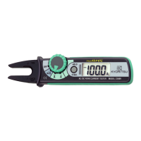
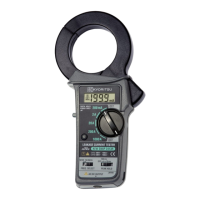
AC/DCFORKCURRENTTESTER
KEW
2300R
KEW FORK
Co
rre
ct
Wrong
2. Features
●
Thisinstrument,Forkcurrenttester,canmeasureAC/DCcurrentupto100Awithoutopening
andclosingtheJaws.
●
TrueRMSreadingforACcurrent
●
Forkshapedsensorforeasymeasurementattightplacesandcrowdedcableareas.
●
NCVfunction(NonContactVoltage)enableslivewirecheck
●
Autopowerofffunction
●
Dataholdfunction
●
Pocketsizehandytester,adoptedover-moldingforabetterfit
●
Carryingcasefurnishedasastandardaccessory.
●
Designedtointernationalsafetystandards.
IEC61010-2-032measurementCAT.III300VPollutiondegree2
○
MeasurementCategory
Toensuresafeoperationofmeasuringinstruments,IEC61010establishessafetystandards
for various electrical environments, categorized as O to CAT IV, and called measurement
categories. Higher-numbered categories correspond to electrical environments with greater
momentaryenergy,soameasuringinstrumentdesignedforCATIIIenvironmentscanendure
greatermomentaryenergythanonedesignedforCATII.
O :Circuitswhicharenotdirectlyconnectedtothemainspowersupply.
CATII :ElectricalcircuitsofequipmentconnectedtoanACelectricaloutletbyapower
cord.
CATIII :Primaryelectricalcircuitsoftheequipmentconnecteddirectlytothedistribution
panel,andfeedersfromthedistributionpaneltooutlets.
CATIV :Thecircuitfromtheservicedroptotheserviceentrance,andtothepowermeter
andprimaryover-currentprotectiondevice(distributionpanel).
O: Device which is
not directly
connected to the
mains power supply
Barrier:It is a part providing protection against electrical shock and ensuring the minimum
requiredairandcreepagedistances.
KYORITSU ELECTRICAL INSTRUMENTS
WORKS, LTD.
#