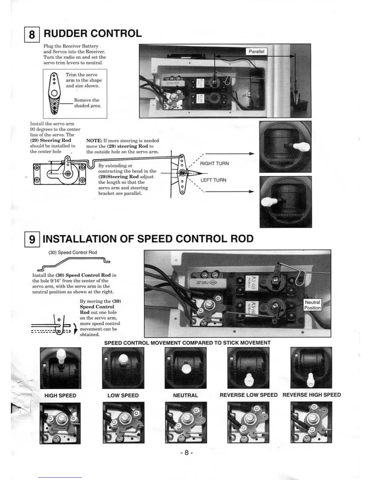
[I) RUDDER CONTROL
Plug the Receiver Battery
and Servos
iniAl
the Receiver.
Turn
the
radio on and
set
the
servo trim levers
to neutral.
0
0
0
0
Trim
lhe
servo
arm
IAl
the shape
and
size shown.
In
sta
ll
the servo
arm
90 degrees
IAl
the
center
line
of
the servo.
The
(
29
) S
teering
Rod
should be
instal
led in
the
center
hole
NOTE: If more steering is needed
move the
(
29
)
stee
r
ing
Rod
to
the outside hole on
the
servo arm.
By
extending
or
contracting
the
bend in the
(29)S
tee
rin
g
Rod
adjust
the
length so
that
lhe
servo
arm
and
steering
bracket
are
parallel.
Install
th
e (30) Speed
Co
nt
ro
l
Ro
d in
the hole 9/16
'"
from
the
center
of
the
servo arm, with the servo arm
in
lhe
neutral position
as
shown
at
the right.
0
By
moving
the
(3
0)
Spe
ed
Control
Ro
d
out
one hole
on
the servo
arm,
\ m
o•·e
speed cont•·ol
~,
, mov7ment can
be
obtained.
'
'
,
'
---------------
~
, ' RIGHT TURN
•,
LE
FT
TURN
'
'
'
· - - -
---
-
r·
.~,
•
SPEED CONTROL MOVEMENT COMPARED TO STI
CK
MOVEMENT
...,
-
'
r
l
HIGH SPEED LOW SPEED NEUTRAL
REVERSE LOW SPEED REVERSE HIGH SPEED
- 8 -