L-ACOUSTICS XT Manual V1.1 2/11/2003 4
LIST OF FIGURES
Figure 1: XT System Components .................................................................................................................... 8
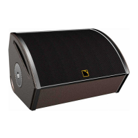
Figure 2: 112XT Enclosure.............................................................................................................................. 10
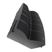
Figure 3: 115XT Enclosure.............................................................................................................................. 11
Figure 4: MLS switches on the rear panel of L-ACOUSTICS LA24a, LA48a amplifiers..................................14
Figure 5: L-ACOUSTICS preset library for XTA DP224 ................................................................................ 21
Figure 6: L-ACOUSTICS preset library for XTA DP226 ................................................................................ 22
Figure 7: L-ACOUSTICS preset library for BSS FDS-334 Minidrive ...............................................................23
Figure 8: L-ACOUSTICS preset library for BSS FDS-336 Minidrive ...............................................................24
Figure 9: L-ACOUSTICS preset library for BSS FDS-366 Omnidrive Compact Plus ....................................25
Figure 10: General guidelines for aiming XT enclosures.................................................................................27
Figure 11: SPL mappings at octave band frequencies for a single XT enclosure............................................. 27
Figure 12: SPL mappings at octave band frequencies for two XT enclosures with 0.5 metre spacing........... 28
Figure 13: SPL mappings at octave band frequencies for two XT enclosures with 3 metre spacing.............. 28
Figure 14: General guidelines for arraying XT enclosures.. ............................................................................29
Figure 15: SPL mappings at octave band frequencies for four XT enclosures with 0.5 metre spacing........... 29
Figure 16: L-ACOUSTICS Subwoofer Continuous Unweighted SPL Comparison......................................... 34
Figure 17: Illustration of subwoofer time alignment........................................................................................ 36
Figure 18: ETR112XT, ETR115XT U-bracket installation procedure ............................................................ 38
Figure 19: CPL112XT, CPL115XT coupling adapter installation procedure.................................................. 39
Figure 20: XTLIFTBAR installation procedure ................................................................................................40
Figure 21: 112XT Line Drawing......................................................................................................................44
Figure 22: 112XT + ETR112XT Line Drawing............................................................................................... 45
Figure 23: 112XT + XTLIFTBAR Line Drawing............................................................................................. 45
Figure 24: 112XT + ETR112XT + 112CPLXT Line Drawing (0 degree) .....................................................46
Figure 25: 112XT + ETR112XT + 112CPLXT Line Drawing (30 degrees)..................................................46
Figure 26: 115XT Line Drawing......................................................................................................................48
Figure 27: 115XT + ETR115XT Line Drawing............................................................................................... 49
Figure 28: 115XT + XTLIFTBAR Line Drawing............................................................................................. 49
Figure 29: 115XT + ETR115XT + 115XTCPL Line Drawing (0 degrees)....................................................50
Figure 30: 115XT + ETR115XT + 115XTCPL Line Drawing (30 degrees)..................................................50
LIST OF TABLES
Table 1: Load and Power Ratings for 112XT ..................................................................................................12
Table 2: Recommended power amplification and MLS switch settings for 112XT low section .....................13
Table 3: Recommended power amplification and MLS switch settings for 112XT high section ....................13
Table 4: Recommended MLS switch settings for powering 112XT................................................................ 14
Table 5: Load and Power Ratings for 115XT ..................................................................................................14
Table 6: Recommended power amplification and MLS switch settings for 115XT low section .....................15
Table 7: Recommended power amplification and MLS switch settings for 115XT high section ....................15
Table 8: Recommended MLS switch settings for powering 115XT................................................................ 15
Table 9: Output Power Ratings and MLS Switch Settings for L-ACOUSTICS LAa Amplifiers .......................16
Table 10: Maximum Recommended Length for Damping Factor > 20.......................................................... 17
Table 11: Nominal floor monitor distance and monitor separation versus performer height ........................ 33
Table 12: L-ACOUSTICS Subwoofer Specification Summary......................................................................... 34