EasyManua.ls Logo

L-TEC PCM-70 - Page 6

L-TEC PCM-70
12 pages
Print Icon
To Next Page IconTo Next Page
To Previous Page IconTo Previous Page
Loading...
NOTES:
1.
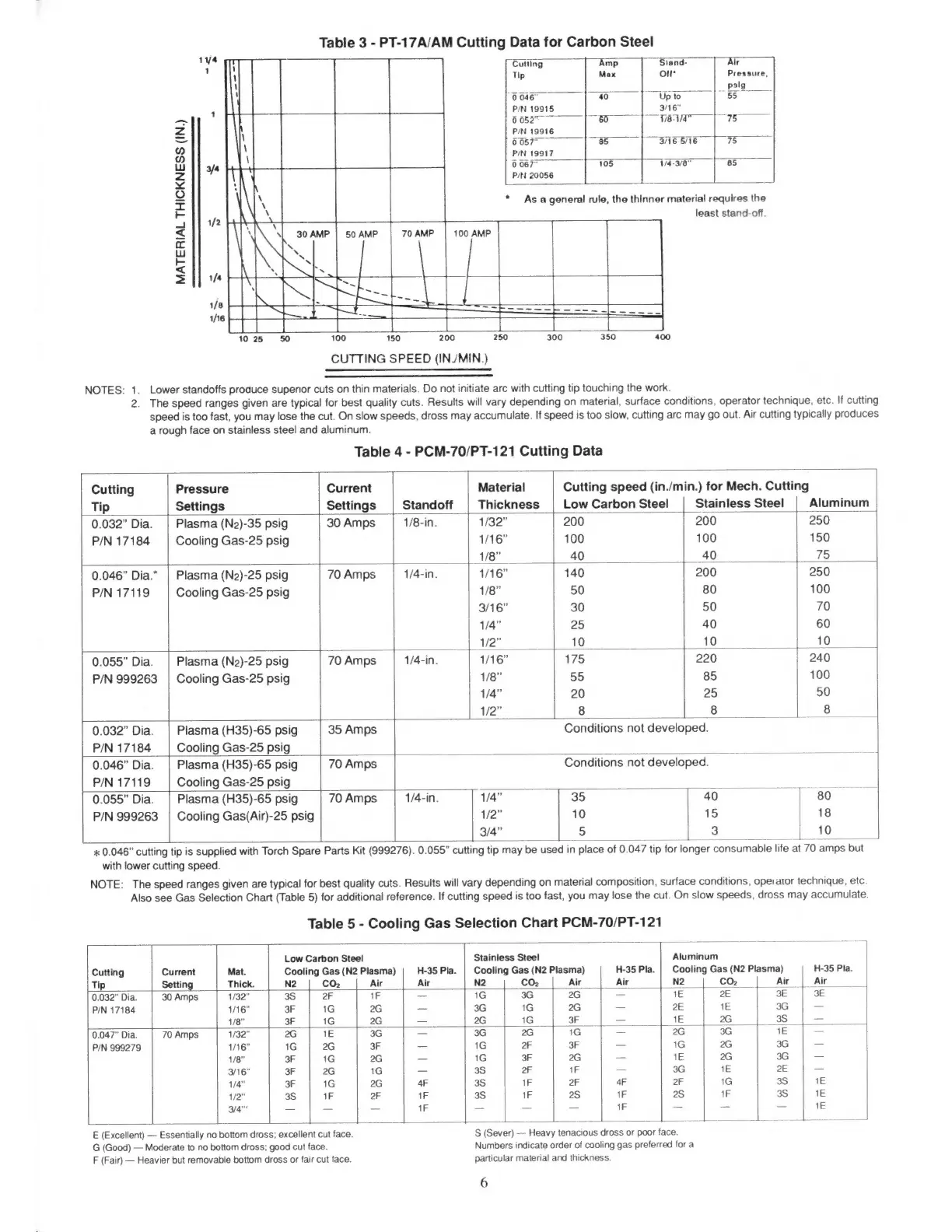
Table
3
-
PT-17A/AM
Cutting
Data
for
Carbon
Steel
ut
Cutiing
“Amp
Stand
Air
Tip
Max
o
Pressure,
psig
0046”
40
Up
to
ES
1
P/N
19915
3/16"
SC
00527
|
&
|
I8ä"
|
75
z
P/N
19916
a
0057
85
3/16
5/16
75
H
P/N
19917
Ww
3/4
0
067"
105
1/4-3/8"
85
z
P/N
20056
$
I
As
a
general
rule,
the
thinner
material
requires
the
T
1/2
least
stand-off.
Es
100
AMP
c
Lu
Lr
«
zl
UO.
ege
E
SE
tS
sie
EEE
250
JL
150
100
200
300
350
400
CUTTING
SPEED
(IN/MIN.)
Lower
standoffs
produce
superior
cuts
on
thin
materials.
Do
not
initiate
arc
with
cutting
tip
touching
the
work.
2.
The
speed
ranges
given
are
typical
for
best
quality
cuts.
Results
will
vary
depending
on
material,
surface
conditions,
operator
technique,
etc.
If
cutting
speed
is
too
fast,
you
may
lose
the
cut.
On
slow
speeds,
dross
may
accumulate.
If
speed
is
too
slow,
cutting
arc
may
go
out.
Air
cutting
typically
produces
a
rough
face
on
stainless
steel
and
aluminum.
Table
4
-
PCM-70/PT-121
Cutting
Data
Cutting
Pressure
Current
Material
Cutting
speed
(in./min.)
for
Mech.
Cutting
Tip
Settings
Settings
Standoff
Thickness
|
Low
Carbon
Steel
Stainless
Steel
Aluminum
0.032"
Dia.
|
Plasma
(N2)-35
psig
30
Amps
1/8-in.
1/32"
200 200
250
P/N
17184
Cooling
Gas-25
psig
1/16"
100
100 150
1/8"
40 40
75
0.046"
Dia.”
|
Plasma
(N2)-25
psig
70Amps
|
1/4-in.
116"
140
200
250
P/N
17119
Cooling
Gas-25
psig
1/8"
50
80
100
3/16"
30
50
70
1/4"
25
40
60
|
1/2”
10 10
u
10
0.055"
Dia.
Plasma
(N2)-25
psig
70
Amps
1/4-in.
1/16”
175
|
220 240
P/N
999263
|
Cooling
Gas-25
psig
1/8"
55 85
100
1/4"
20
25 50
1/2"
8
|
8
|]
8
E
0.032"
Dia.
|
Plasma
(H35)-65
psig
35
Amps
Conditions
not
developed.
P/N
17184
Cooling
Gas-25
psig
7
u
0.046"
Dia.
|
Plasma
(H35)-65
psig
70
Amps
Conditions
not
developed.
-
o
`
P/N
17119
Cooling
Gas-25
psig
0.055"
Dia.
|
Plasma
(H35)-65
psig
70Amps
|
1/4-in.
1/4"
35
.40
|
|
80
E
P/N
999263
|
Cooling
Gas(Air)-25
psig
1/2"
10
15
18
3/4"
5
3
10
|
x
0.046"
cutting
tip
is
supplied
with
Torch
Spare
Parts
Kit
(999276).
0.055"
cutting
tip
may
be
used
in
place
of
0.047
tip
for
longer
consumable
life
at
70
amps
but
with
lower
cutting
speed.
NOTE:
The
speed
ranges
given
are
typical
for
best
quality
cuts.
Results
will
vary
depending
on
material
composition,
surface
conditions,
operator
technique,
etc.
Also
see
Gas
Selection
Chart
(Table
5)
for
additional
reference.
If
cutting
speed
is
too
fast,
you
may
lose
the
cut.
On
slow
speeds,
dross
may
accumulate.
Table
5
-
Cooling
Gas
Selection
Chart
PCM-70/PT-121
Low
Carbon
Steel
Stainless
Steel
Aluminum
Cutting
Current
Mat.
Cooling
Gas
(N2
Plasma)
H-35
Pla.
Cooling
Gas
(N2
Plasma)
H-35
Pla.
Cooling
Gas
(N2
Plasma)
H-35
Pla.
Tip
Setting
Thick.
N2
CO2
Air
Air
N2
CO;
Air
Air
N2
|
CO
|
Ai
|
Air
`
0.032"
Dia.
|
30
Amps
1/32"
3S
|
2F
1F
=
iG
3G
G
|
=
ve
|
2E
3E
|
3E
P/N
17184
1/16"
3F
1G
2G
SS
3G
1G
2G
2E
1E
3G
1/8"
3F
1G
2G
-—
2G
1G
3F
1E
2G
(39
|
0.047"
Dia.
70
Amps
1/32"
2G
1E
3G
3G
2G
1G
2G
3G
1E
P/N
999279
1/16”
1G
2G
3F
1G
2F
3F
=
1G
2G
3G
=
1/8"
3F
1G
2G
=
1G
3F
2G
1E
2G
3G
e
3/16"
3F
2G
1G
3S
2F
1F
=
3G
1E
2E
1/4"
3F
1G
2G
4F
3S
1F
2F
4F
2F
1G 3S
1E
1/2”
3S
1F
2F
1F
3S
1F
2S
1F
28
1F
3S
1E
3/4"
=
1F
1F
1E
S
S
a
ol
——
E
(Excellent)
Essentially
no
bottom
dross;
excellent
cut
face.
G
(Good)
Moderate
to
no
bottom
dross;
good
cut
face.
F
(Fair)
Heavier
but
removable
bottom
dross
or
fair
cut
face.
S
(Sever)
Heavy
tenacious
dross
or
poor
face.
Numbers
indicate
order
of
cooling
gas
preferred
for
a
particular
material
and
thickness.
6