EasyManua.ls Logo

L-TEC PCM-70 - Page 9

L-TEC PCM-70
12 pages
Print Icon
To Next Page IconTo Next Page
To Previous Page IconTo Previous Page
Loading...
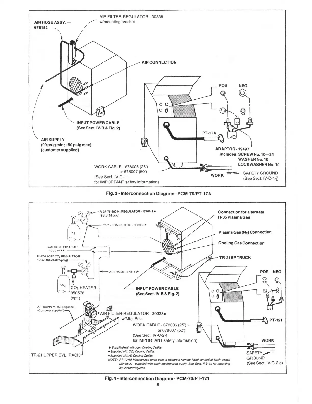
AIR
FILTER-REGULATOR
-
30338
AIR
HOSE
ASSY.
w/mounting
bracket
678152
AIR
CONNECTION
INPUT
POWER
CABLE
(See
Sect.
IV-B
&
Fig.
2)
AIR
SUPPLY
(90
psig
min;
150
psig
max)
(customer
supplied)
ADAPTOR
-
19497
includes:
SCREW
No.
10—24
WASHER
No.
10
WORK
CABLE
-
678006
(25’)
ei
=
LOCKWASHER
No.
10
or
678007
(50')
á
SAFETY
GROUND
(See
Sect.
IV-C-1-i
(See
Sect.
IV-C-1-j)
for
IMPORTANT
safety
information)
R-27-75-580
N;
REGULATOR
-
17166
ée
Connection
for
alternate
(Set
at
25
psig)
H-35
Plasma
Gas
“Y”
-
CONNECTOR
-
950356
Plasma
Gas
(N2)
Connection
Cooling
Gas
Connection
GAS
HOSE
(12-1/2-ft.)
40V77*€"e
R-27-75-320
CO;
REGULATOR
-
17855m
(Set
at
25
psig)
TR-21SP
TRUCK
<—
AIR
HOSE
-
678152%
POS
NEG
CO2
HEATER
-
INPUT
POWER
CABLE
950578
(See
Sect.
IV-B
&
Fig.
2)
(opt.)
AIR
SUPPLY
(150
psig
max.)
Ss
(Customer
supplied)
v
A
X
E
á
w/Mtg.
Brkt.
WORK
CABLE
-
678006
(25')
or
678007
(507)
(See
Sect.
IV-C-2-f
for
IMPORTANT
safety
information)
Supplied
with
Nitrogen
Cooling
Outfits.
u
Supplied
with
CO»
Cooling
Outfits.
=
TR-21
UPPER
CYL.
RACK
e
Supplied
with
Air
Cooling
Outfits.
SAFETY
e"
NOTE:
PT-121M
Mechanized
torch
uses
a
separate
remote
hand
controlled
torch
switch
GROUND
(2075600
-
supplied
with
each
mechanized
outfit).
See
Sect.
II-B-1c
for
mounting
(See
Sect.
IV-C-2-g)
equipment
required.
S
Fig.
4
-
Interconnection
Diagram
-
PCM-70/PT-121
9