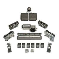
Fix the second mechanical limit switch (10) in the centre of the transom in case of double leaf and only if the electric
lock is not present, as per fig. 3, using screws M6 x 10 with washers M6.
Apply the rubber buffer on the outer lh border of the limit switch.
This mechanical limit switch corresponds to the closing limit switch in case of double leaf door.
In case of single leaf door, fasten the mechanical limit switch to the right side of the transom, as per fig. 4 and 5.
This mechanical limit switch corresponds to the opening limit switch in case of single leaf door with rightward
opening, and to the closing limit switch in case of single leaf door with leftward opening without electric lock.
Fix the idle pulley (9) to the right side of the transom,
as per fig. 3, 4, 5 using screws M6x10.
16
17
Fix the motor assembly with encoder (3) to the right
side of the transom as per fig. 3, 4, 5 using screws
M6x10.
18
If required, fix the battery plate under the electronic control unit container, by fastening it with No. 2 t.c.c. screws 3.9 x
6.5 and place the emergency battery on it.
19
20
Fix the electronic control unit (2) to the right side of the transom, as per fig. 3, 4, 5 using screws M6x8.
Connect, to the electronic control unit, the motor cable, the encoder cable and the negative pole of the battery; the positive pole
will be connected after the automated equipment start-up.
The Battery charger board shall be inserted in the connector J1 of the electronic control unit.
21
22
10
16
17 18
19
20
21
22
 Loading...