Do you have a question about the Label NEPTIS PLUS and is the answer not in the manual?
Detailed instructions for assembling the automation on the transom from the hinge side.
Detailed instructions for assembling the automation on the transom from the hinge side.
Detailed instructions for assembling the automation on the transom from the hinge side.
Instructions for assembling the automation on the transom from the side opposite the hinge.
Instructions for assembling the automation on the leaf from the hinge side.
Instructions for assembling the automation on the transom from the hinge side.
Step-by-step assembly guide for the SLIDE PULL ARM BDT2.
Step-by-step assembly guide for the SLIDING ELBOW ARM BSG 150/250.
Instructions for assembling the sliding guide for the pull arm.
Assembly instructions for the BSS2 ARTICULATED PUSH ARM.
Instructions for using the EXTC-Z extension for the EXTB-Z tapered pin.
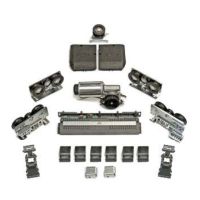
List of necessary tools for installation.
Procedure for checking the automation after unpacking.
Guidance on selecting the appropriate spring re-closing force.
Instructions for inserting the arm tapered pin into the output shaft.
Procedure for releasing the spring, with safety warnings.
Detailed wiring diagram for connecting various components to the PWB.
Detailed description of the PWB module, terminals, and connection steps.
Purpose and connection details for the ET-DSEL digital selector.
Wiring and DIP switch settings for the OA-EDGE T safety sensor.
Wiring and DIP switch settings for the FLAT SCAN safety sensor.
Procedure for the initial start-up and language selection of the digital selector.
Settings for serial communication between the selector and the automation.
Mandatory step for first installation, setting up door type, lock, and sensors.
How to perform functional tests to ensure correct operation after setup.
Checking the status of inputs and connected devices using the ET-DSEL selector.
Explanation of the 3-position manual program selector modes.
Description of the 5-position mechanical key selector and its connections.
Using the digital selector ET-DSEL as a program selector for door modes.
How to set and change function statuses (ON/OFF) using the digital selector.
How to adjust parameters using potentiometers via the digital selector.
Step-by-step guide to changing the technical password.
Step-by-step guide to changing the primary (owner) password.
Step-by-step guide to changing the service password.
How to enable password protection for user access.
How to disable user password protection.
Option for factory setting of functions and parameters for single-leaf doors.
Setup for enabling and managing electric locks or strikes.
Setup for enabling and managing electromagnets.
Electrical connections for dual-leaf door setup.
Commissioning steps for dual-leaf doors, including dip-switch settings.
Functional testing procedures for dual-leaf doors.
How to enable and use the partial opening function for dual-leaf doors.
Specific considerations for using the ET-DSEL selector with two-leaf doors.
Checking input status for master/slave automations.
Diagram and steps for the electrical interlock connections.
Explanation of how the interlock system operates with two doors.
Using a single internal detector for interlock applications.
Interlock application with electric locks disabled in closed doors.
Electrical connections for privacy function accessories like touch buttons and lights.
How the privacy system operates, including signaling lights and user interaction.
Configuration settings (Functions F77-F79, Potentiometers P34-P35) for the privacy function.
| Brand | Label |
|---|---|
| Model | NEPTIS PLUS |
| Category | Door Opening System |
| Language | English |