61
29) NB-BAT BATTERY MODULE
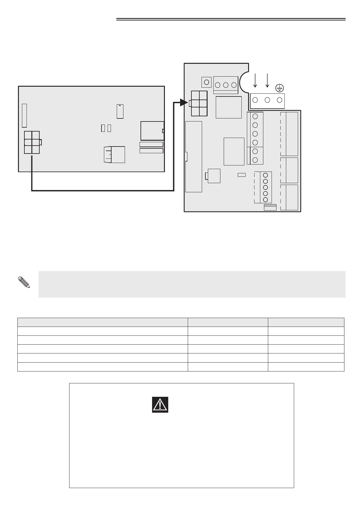
Electric connection
Connect the J1 connector of the NB-BAT module to the J3 connector of the PWB power supply unit through the special cables.
The battery cable must be connected to the J2 connector of the NB-BAT module.
Operation
The NB-BAT module trips in case of mains power failure, allowing the Neptis Plus automation to keep running.
Battery life depends on various factors, on the number of manoeuvres carried out, on the weight of the leaf, on the external devices
connected, etc.
As a rough guide, the charged battery can supply power for about 50 consecutive door opening/closing cycles, or for about two hours
with the door stopped.
IMPORTANT!
BATTERY TYPE: 3x6V (18V) - 1,3Ah
LED SIGNALLING
SIGNALLED EVENTS GREEN LED RED LED
BATTERY DISCONNECTED ON ON
BATTERY CHARGING BLINKING OFF
BATTERY CHARGED WITH MAINS VOLTAGE ON OFF
BATTERY LOW OFF BLINKING
BATTERY CHARGED WITHOUT MAINS VOLTAGE OFF ON
WARNING!
•
Periodically check battery eciency
•
To allow recharging, the batteries must always be connected to the electronic control
unit
•
The equipment must be disconnected from the mains when removing the batteries
•
In case of replacement, always use genuine batteries
•
Replacement must be performed by qualied personnel
•
Remove batteries from the equipment before their disposal
•
Batteries contain polluting substances; therefore they must be disposed of in
accordance with the provisions of local regulations
J1
NB-BAT
connections card
AUX1
E.C. (safety sensor in closing)
COMMON
AUX2
E.O. (safety sensor in opening)
OPEN
COMMON
DIGITAL
PROGRAMMER
ET-DSEL
RADAR EX
RADAR IN
START
COMMON
AUX1
E.C.
COMMON
AUX2
E.O.
OPEN
COMMON
RADAR EX
RADAR IN
START
COMMON
ET-DSEL
DIGITAL
PROGRAMMER
M6
TEST
GND
AUX3
24V
O.C.
24V
L1
J5
M4
T-NFC
J1
25
26
27
28
29
8
9
10
11
+
A
B
-
1
2
3
4
5
6
7
J4
START
PS1
F N
115/230V
M1
M2
RL3
M8
M5
M7
21
20
19
18
17
16
+
NC
NO
C
+
-
OUT
24V
LOCK
M3
RL1
NA
24
NC
23
C
22
J3
CONNECTOR
BATTERY
MP1
J2
-
+
PT2
PT3
MFT2
LED
RED GREEN
PT1