Do you have a question about the Label NEPTIS/LE and is the answer not in the manual?
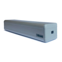
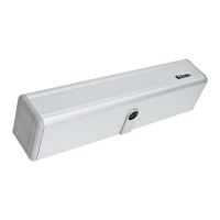
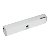
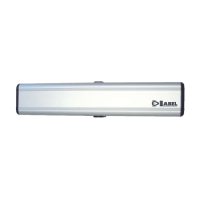
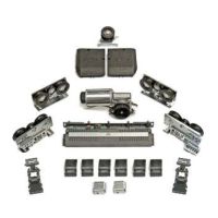
Identifies and lists the main parts of the swing door actuator.
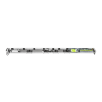
Details the different types of arms (sliding and articulated) for the actuator.
Provides crucial safety guidelines for installing and using the actuator.
Outlines obligations for installers regarding the machine directive.
Explains the general capabilities and usage of the NEPTIS/LE actuator.
Step-by-step guide for preparing and physically mounting the actuator.
Provides dimensional and graphical representations of the actuator and arms.
Details the process of connecting the actuator arm to the door.
Instructions on how to safely detach the actuator arm.
Explains the use and installation of an optional extension shaft.
Illustrates wiring diagrams for power and control inputs of the unit.
Describes the components and functions of the main control logic board.
Procedure to reset the spring preload if accidentally released.
Guides through the mandatory initial configuration process for operation.
Explains how to use manual selectors for operating modes.
Details the functions controlled by the DIP switches on S1.
Details the functions controlled by the DIP switches on S2, often via digital selector.
Describes how to adjust operating parameters using potentiometers.
Explains the operation and features of the digital selector interface.
Enables a special opening function for disabled persons.
Describes how to enable electro-lock release for manual door operation.
Details the installation and configuration of photocell safety sensors.
Instructions for configuring and installing the system for double-wing doors.
Enables a specific opening function for pedestrian access on double-wing doors.
Lists selectable parameters for MASTER and SLAVE control units.
Explains the different audible signals (beeps) from the control unit.
Provides key technical data like power supply, temperature, and protection degree.
Details how to access and adjust advanced operating parameters via the technical menu.
| Brand | Label |
|---|---|
| Model | NEPTIS/LE |
| Category | Door Opening System |
| Language | English |