Do you have a question about the Label NEXT 120s and is the answer not in the manual?
Explains symbols like Danger, Warning, and Note for safety instructions.
Covers installation by specialists, structural stability, child safety, intended use, and environmental conditions.
Lists necessary tools for installation, including tape measure, drill, screwdrivers, and Allen wrenches.
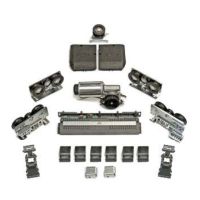
Details steps to prepare the automation unit by removing covers and components.
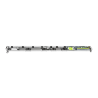
Presents detailed diagrams and dimensions for the sliding pull arm installation.
Provides technical drawings and dimensions for installing the sliding push arm.
Shows installation diagrams and dimensions for the articulated push arm.
Details technical drawings and dimensions for the elbow sliding pull arm (150mm).
Presents technical drawings and dimensions for the elbow sliding pull arm (250mm).
Illustrates how to mount the leaf for the NEXT120-BAS automation.
Describes the shaft extension pivot and its application for increasing automation-arm distance.
Details wiring for power supply, OA-EDGE T safety sensors, external and internal radars.
Shows connections for manual program selector, NEXT-120S control unit, and the digital selector ET-DSEL.
Describes how to connect and set up the OA-EDGE T safety sensor with the control unit.
Details the wiring and setup for the Flat Scan safety sensor with the control unit.
Guides on the initial power-up and language selection for a new ET-DSEL selector.
Details how the ET-DSEL selector detects and stores the automation's serial code.
Details the operation of the 3-position manual program selector integrated into the automation.
Explains the 5-position mechanical key selector as an alternative program selector.
Explains how to set and change various functions of the automation.
Details how to adjust parameters using potentiometers for functions like opening speed and closing speed.
Provides step-by-step instructions for changing the technical password.
Details the process for changing the primary password for the system owner-user.
Explains how to change the service password, typically provided to authorized users.
Guides on how to enable the usage of primary and service passwords.
Describes the procedure to disable the usage of user passwords, making access free.
Allows choosing which work programs are displayed on the digital selector for end-user selection.
Describes the Plug and Play option for setting functions/parameters at the factory before shipping.
Details setup functions and parameters for enabling electric locks and strikes.
Explains setup functions and parameters for enabling the use of electromagnets.
Covers electrical connections for dual leaf doors, connecting Master/Slave automations and accessories.
Details the commissioning process for dual leaf doors, including dip-switch settings and setup.
Guides on performing functional tests for dual leaf doors, checking leaf movement and safety sensors.
Explains how to enable and use the partial opening option for dual leaf doors.
Details how to adjust functions and parameters separately for Master and Slave automations.
Explains how to access maintenance functions for Master and Slave automations.
Describes viewing information and events separately for Master and Slave automations.
Guides on checking input status for Master and Slave automations using the ET-DSEL.
Covers installation, use of radio control, memory erasure, and technical specifications of the NEXT-RX receiver.
Details the wiring diagram for connecting two automatic doors to enable interlock operation.
Explains the operational logic of the interlock system, including radar usage and door opening sequences.
Describes how to use the interlock system with electric locks disabled in specific conditions.
Illustrates the wiring connections for the privacy function, including sensors, traffic lights, and maglock.
Details the settings for activating and configuring the privacy function, including traffic light status.
Explains specific function (F77, F78, F79) and potentiometer (P34, P35) settings related to the privacy function.
| Brand | Label |
|---|---|
| Model | NEXT 120s |
| Category | Door Opening System |
| Language | English |