20
8) SAFETY SENSORS
This section describes how to connect and setup correctly some of the safety sensors compliant with the standard EN12987 available on
the market, to ensure a safety level which corresponds to PL = c, Category 2 as provided for by the standard EN16005.
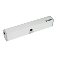
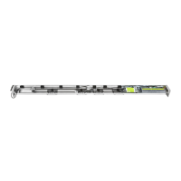
8.1) SAFETY SENSOR OA-EDGE T
This section describes how to connect and setup the safety sensors in accordance with the standard EN16005.
WIRING CONNECTION OF SENSOR OA-EDGE T CONNECTION OF AUTOMATION NEXT 120S WIRING
Wiring between the sensor and the terminal of the control unit NEXT-L120S
1. WHITE (+) Power supply TERMINAL 24 (+)
2. BROWN (‑) Power supply TERMINAL 0 (‑)
3. GREEN COM (Closing side) TERMINAL 0 COM
4. YELLOW N.C. (Closing side) TERMINAL 7 Closing safety sensor
5. GREY N.O. (Closing side) do not connect
6. PINK COM (Opening side) TERMINAL 0 COM
7. BLUE N.C. (Opening side) TERMINAL 6 Opening safety sensor
8. RED N.O. (Opening side) do not connect
9. BLACK (+) Test input TERMINAL T TEST(+)
10. VIOLET (‑) Test input TERMINAL 0 GND (‑)
DIP SWITCH SETTING ON OA-EDGE T PARAMETERS ON DIGITAL SELECTOR ET-DSEL
A7 = ON Low level test input.
A8 = OFF Input test delay 10msec.
B4 = OFF Sensor installed on opening side.
B4 = ON Sensor installed on closing side.
F11 (S05) = ON Closing safety sensor
F12 (S06) = ON Opening safety sensor
F13 (S07) = ON TEST of opening safety sensor
F14 (S08) = ON TEST of opening safety sensor
F15 (S09) = OFF Test level LOW
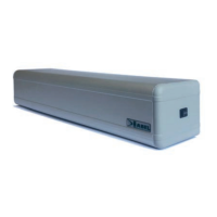
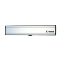
8.2) FLAT SCAN SAFETY SENSOR
CONNECTION OF FLAT SCAN SENSOR WIRING CONNECTION OF AUTOMATION NEXT 120S WIRING
Wiring between the sensor and the terminal of the control unit NEXT-L120S
1. GREEN (+) Power supply TERMINAL 24 (+)
2. BROWN (‑) Power supply TERMINAL 0 (‑)
3. YELLOW COM (Opening side) TERMINAL 0 COM
4. WHITE N.C. (Opening side) TERMINAL 6 Opening safety sensor
5. PINK COM (Closing side) TERMINAL 0 COM
6. GREY N.C. (Closing side) TERMINAL 7 Closing safety sensor
7. RED (+) Test input TERMINAL T TEST(+)
8. BLUE (‑) Test input TERMINAL 0 GND (‑)
DIP SWITCH SETTING ON FLAT SCAN PARAMETERS ON DIGITAL SELECTOR ET-DSEL
DIP 1 ON Sensor installed on opening side.
DIP 1 OFF Sensor installed on closing side.
F11 (S05) = ON Closing safety sensor
F12 (S06) = ON Opening safety sensor
F13 (S07) = ON TEST of opening safety sensor
F14 (S08) = ON TEST of opening safety sensor
F15 (S09) = OFF Test level LOW
 Loading...