Do you have a question about the Label ETERNA 90 EASY and is the answer not in the manual?
Provides warnings about installation, use, and potential dangers.
Lists installer and user responsibilities for safe operation.
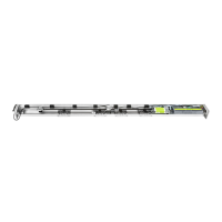
Details ETERNA 90 EASY D and S automation models and their uses.
Lists key technical data like power, speed, and dimensions.
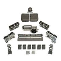
Illustrates and lists the various parts of the automation system.
Provides diagrams and formulas for double and single leaf configurations.
Details the procedure for installing and removing the automation's covering casing.
Explains how to adjust the belt tension for optimal performance.
Guides on setting the mechanical limit switch for accurate stopping.
Details the process of attaching and adjusting the door leaves to the carriages.
Provides essential dimensions and required tools for installation.
Covers electric lock types, positioning, connection, and manual release.
Describes FAIL SAFE and FAIL SECURE electric lock types.
Guides on positioning and connecting the electric lock.
Details the manual release system installation and operation.
Guides on installing the manual release mechanism on a wall.
Illustrates electrical connections for accessories and the automation.
Explains cable routing and preparation for connections.
Details the 230Vac mains supply connection and protection.
Describes the 24Vdc output for accessories and its load.
Explains inputs for START, RADAR, and OPEN commands.
Details inputs for closing and opening safety sensors.
Explains AUX1, AUX2 inputs and STOP input configuration.
Guides through the initial setup and stroke learning cycle for automation.
Covers setting functions and potentiometers using dip-switches and the PS3 button.
Guides on adjusting dip-switches and potentiometers using the PS3 button.
Details the functions and settings for DIP-SWITCH S1.
Details the functions and settings for DIP-SWITCH S2.
Details the functions and settings for DIP-SWITCH S3.
Explains the purpose and adjustment of each potentiometer (TM1-TM6).
Outlines procedures for testing the automation's operation and safety.
Explains the meaning of LEDs on the control unit for input status.
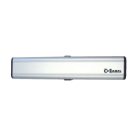
Introduces the T-EASY selector, its installation, and basic usage.
Guides on how to install the T-EASY selector on a wall or metal structure.
Explains how to set up and manage user passwords for the T-EASY selector.
Accessing settings like selector options and language.
Allows customization of operating programs and button functions.
Describes how to select the language for the operating program display.
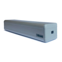
Covers battery types, assembly, and operation for emergency power.
Details the assembly of the ET-BAT90 battery pack.
Details specifications and location of the ET-BAT90P battery pack.
Explains the PRJ38 photocells, their operation, and terminal boards.
Describes the UR24 module for driving air blades or signalling door status.
Details the EN/RF1 radio receiver, installation, and specifications.
Guides on coupling the receiver to the control unit and saving radio controls.
Lists technical details such as power supply, frequency, and range.
Explains the meaning of different buzzer signals from the control unit.
Recommends maintenance operations and checks for safe operation.
Declaration of conformity for the automation as partly assembled machinery.
| Brand | Label |
|---|---|
| Model | ETERNA 90 EASY |
| Category | Door Opening System |
| Language | English |