23
ELECTRIC CONNECTION DESCRIPTION
On the plastic side panels of the ETERNA 90 EASY automation (part 1 in figure in para. 3) there is a hole that must be
broken open, through which the electric cables must be inserted.
Along the upper part of the aluminium transom, there are various plastic cable guides (part 8 in the gure in para. 3) inside
which the cables should be run.
The installer must prepare suitable cable guides on the side panel of the automation control unit for the passage of the
cables and ensure wire stability inside the automation control unit prior to the start-up
of the automatic door, in order to
prevent any contact between the electric cables and the moving parts of the automation.
•
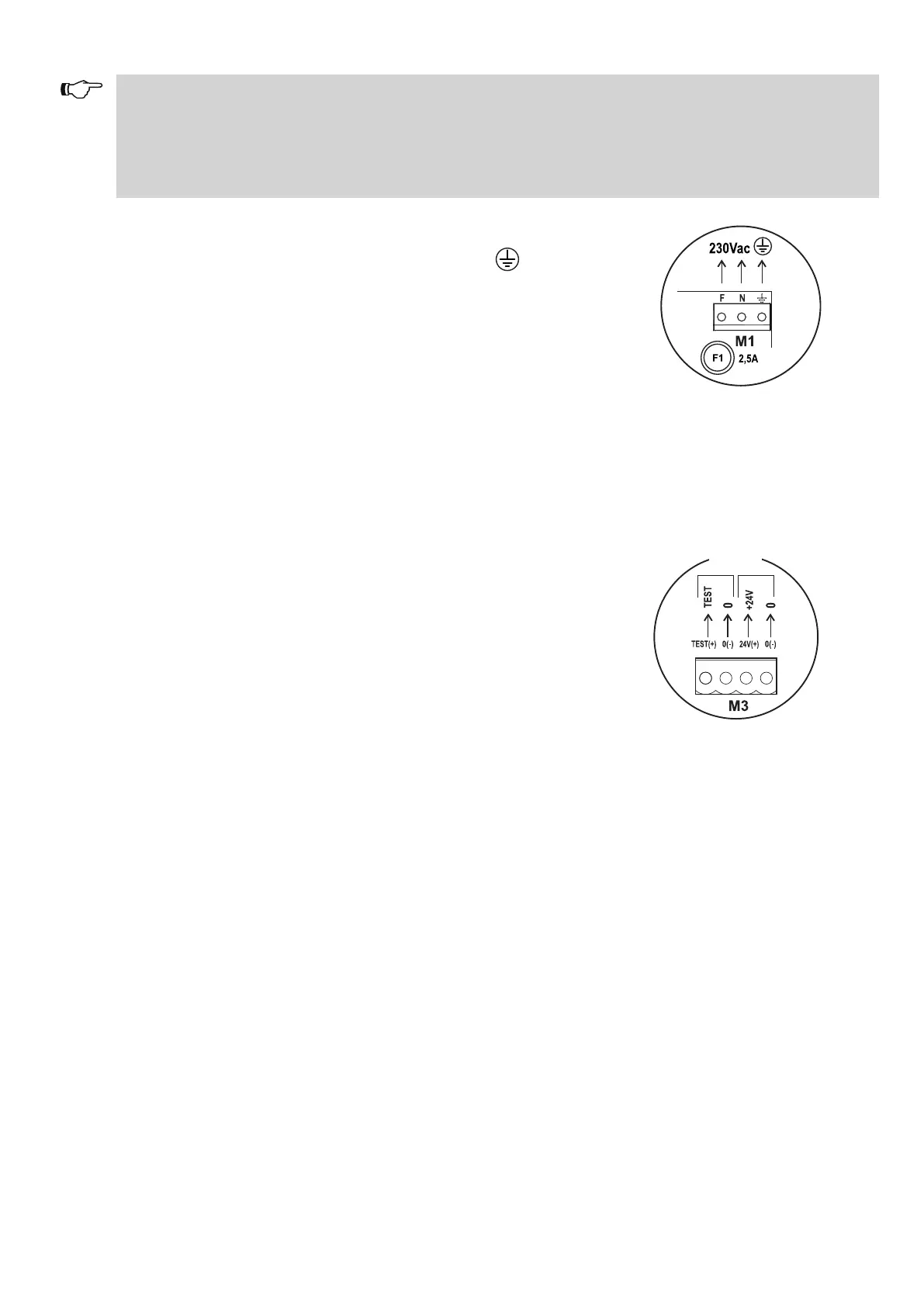
TERMINAL BOARD M1 (F-N-GROUND)
230Vac 50-60Hz mains supply;
phase at terminal F, neutral at terminal N, ground connection at terminal
Ground the automation by connecting the ground cable from the line to one of the
faston connectors to the plate of the motor and control unit module.
Then, using the specific cable, connect the second ground faston to the plate of the
ground terminal onboard the electronic control unit ET-LOGIC-EASY.
The line is protected by the F1 2.5A fuse.
On the power supply mains, provide an omni-polar switch/cut o device with contact
opening distance at least of 3 mm.
The power supply line must be protected against short circuit and leakage to ground.
Separate the 230Vac power supply line from the very-low voltage line control unit
relative to control and safety accessories.
• TERMINAL BOARD M2 (Power supply of external accessories)
24Vdc output for power supply to accessories (radars and sensors).
Max. load 500mA.
19 = Positive terminal +24V.
20 = Negative terminal 0.
The presence of the output voltage is displayed by the Led 1.
17 = Positive
terminal + for TEST safety sensors preset with test function.
18 = Negative terminal 0 for TEST safety sensors preset with test function.
SAFETY SENSORS TESTS
SENSORS POWER SUPPLY
17 18 19 20
• TERMINAL BOARD M5 (Inputs 5, 6, 7, 8, 9)
8 = COMMON
5 = START input. N.O. contact.
The activation opens the door in all operating programs.
6 = INTERNAL RADAR input. N.O. contact.
Activation causes door opening. It is not active when the program selector is set to "Entry only" or to "Night lock".
7 = EXTERNAL RADAR input. N.O. contact.
Activation causes door opening. It is not active when the program selector is set to "Exit only" or to "Night lock".
18 = OPEN input. Input contact logic state can be set to either N.O. or N.C. by dip switch 5 of S2.
The activation opens the door in all operating programs.