16
NOTE:
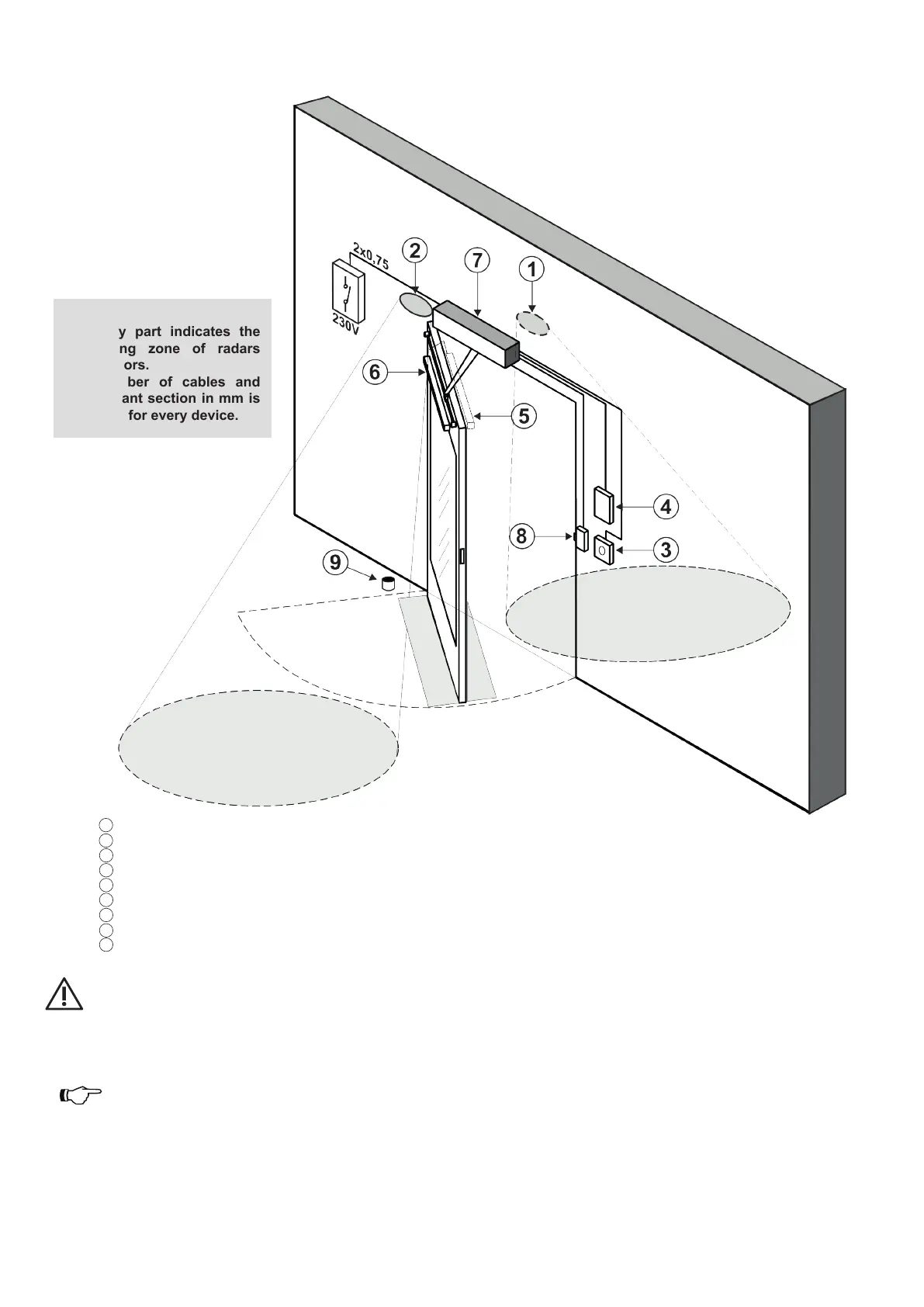
The grey part indicates the
monitoring zone of radars
and sensors.
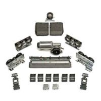
The number of cables and
the relevant section in mm is
indicated for every device.
1 EXTERNAL RADAR (4x0.25mm)
2 INTERNAL RADAR (4x0.25mm)
3 OPENING DEVICE (2X0.25mm)
4 PROGRAM SELECTOR (4X0.25mm)
5 CLOSURE SAFETY SENSOR (6x0.25mm)
6 OPENING SAFETY SENSOR (6x0.25mm)
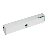
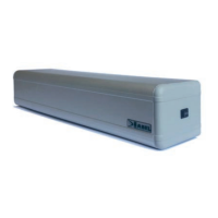
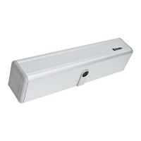
7 AUTOMATION NEXT 120S (mains power 2x0,75mm)
8 ELECTRIC LOCK (2x0.5mm)
9 FLOOR STOP
• The power supply line must be protected against short circuit and leakage to ground.
• On the power supply mains, provide an omnipolar switch/cut o device with contact opening distance of at least 3 mm
• Use self-extinguishing cables for electrical connections.
• Separate the mains power supply line from the very low voltage line control unit relative to control and safety accessories.
• On the plastic side caps of the automation NEXT 120S there are the holes that must be broken open, through which the electric
cables must be inserted.
The installer must take care to secure the power supply cable inside the automation and, in particular, to limit the stripping of the
primary sheath of the cable, so that the surface and air distances do not reduce if a wire comes o the terminal.
• If the automation is installed on a leaf, make the electrical connections using a junction box with suitable commercially available
hoses and exible joints.
ELECTRIC SETUP
 Loading...