18
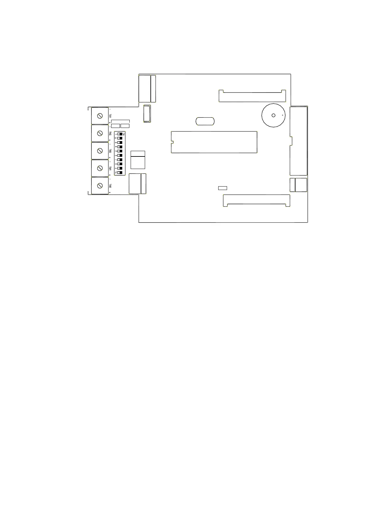
2) DESCRIPTION OF LOGIC PART LGN OF THE CONTROL UNIT
Fig. 2
DL1 DL2 = display the signals from the encoder's sensor.
DL3 = indicates that main microprocessor MP1 is operating correctly by flashing very fast.
If the led is off or flashes slowly, this means that the logic board is faulty.
CONNECTOR J8 = connection for the LOGIC TAST interface module of selector.
CONNECTOR J9 = connector for the photocell board.
CONNECTOR J13 = connection between the MASTER and the SLAVE control unit for two-wing swing door
(see sect. 13). Use the MASTER/SLAVE wiring for "NEPTIS/LE” mod.WR3MS.
CONNECTOR J8 = connection for the LOGIC TAST interface module of selector.
CONNECTOR J9 = connector for the photocell board.
Dip switch S1 = selects the operating programs of the control unit (see sect. 6).
Potentiometer = calibration of the operating parameters (see sect. 8).
Buzzer = horn.
MP1 = microprocessor with label indicating the software version.
BRIDGE J12 = it selects the speed of closing of the door in absence of main power:
OPEN BRIDGE = high speed
CLOSED BRIDGE = low speed
OPENING
SPEED
CLOSING
SPEED
SENSOR
DISTANCE
POWER
PAUSE
LGN-LE
PHOTOCELL CONTROL
BUZZER
LOGIC TAST
MODULO SELETTORE SDN1
NEPTIS-LE
ENCODER
J6
J13
J8
X1
DIP SWITCH
MP1
MOTOR
J7
J10
J9
J11
ENCODER
DL2 DL1
ON
DL3
WD
J12

 Loading...