27
15) SAFETY SENSORS
This section describes how to connect and setup correctly some of the safety sensors compliant with the standard EN12987 available on
the market, to ensure a safety level which corresponds to PL = c, Category 2 as provided for by the standard EN16005.
15.1) SAFETY SENSOR OA-EDGE T
This section describes how to connect and setup the safety sensors in accordance with the standard EN16005.
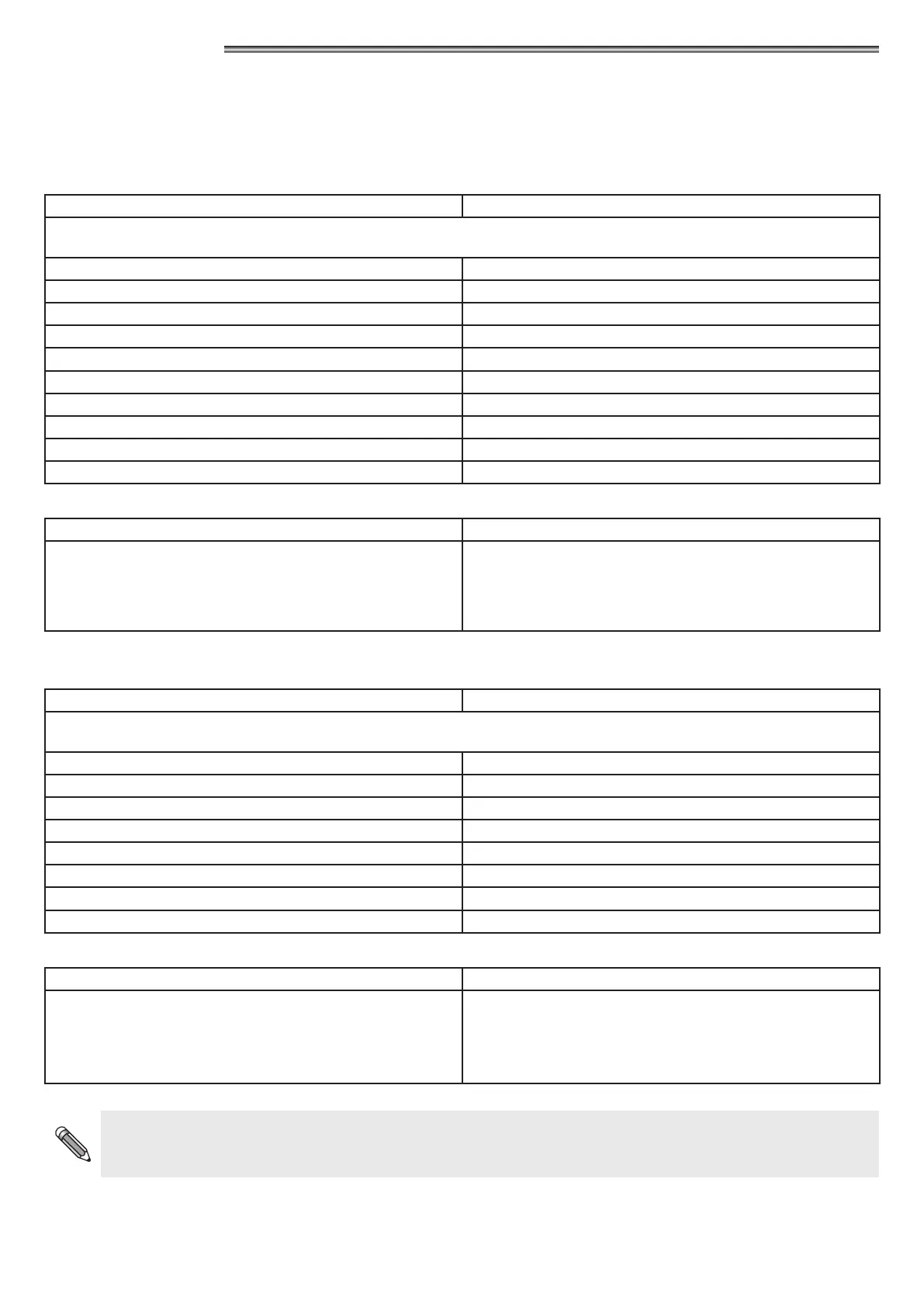
OA-EDGE T SENSOR WIRING Neptis Plus AUTOMATION PWB TERMINAL BOARD
Wiring between the sensor and the terminal of the control unit PWB
1. WHITE (+) Power supply TERMINAL 17 (+)
2. BROWN (-) Power supply TERMINAL 16 (-)
3. GREEN COM (Closing side) TERMINAL 3 COM
4. YELLOW N.C. (Closing side) TERMINAL 2 Closing safety sensor
5. GREY N.O. (Closing side) do not connect
6. PINK COM (Opening side) TERMINAL 7 COM
7. BLUE N.C. (Opening side) TERMINAL 5 Opening safety sensor
8. RED N.O. (Opening side) do not connect
9. BLACK (+) Test input TERMINAL 25 TEST(+)
10. VIOLET (-) Test input TERMINAL 26 GND (-)
DIP SWITCH SETTING ON OA-EDGE T PARAMETERS ON DIGITAL SELECTOR ET-DSEL
A7 = ON Low level test input.
A8 = OFF Input test delay 10msec.
B4 = OFF Sensor installed on opening side.
B4 = ON Sensor installed on closing side.
F11 (S05) = ON Closing safety sensor
F12 (S06) = ON Opening safety sensor
F13 (S07) = ON TEST of closing safety sensor
F14 (S08) = ON TEST of opening safety sensor
F15 (S09) = OFF Test level LOW
15.2) FLAT SCAN SAFETY SENSOR
FLAT SCAN SENSOR WIRING Neptis Plus AUTOMATION PWB TERMINAL BOARD
Wiring between the sensor and the terminal of the control unit PWB
1. GREEN (+) Power supply TERMINAL 17 (+)
2. BROWN (-) Power supply TERMINAL 16 (-)
3. YELLOW COM (Opening side) TERMINAL 7 COM
4. WHITE N.C. (Opening side) TERMINAL 5 Opening safety sensor
5. PINK COM (Closing side) TERMINAL 3 COM
6. GREY N.C. (Closing side) TERMINAL 2 Closing safety sensor
7. RED (+) Test input TERMINAL 25 TEST(+)
8. BLUE (-) Test input TERMINAL 26 GND (-)
DIP SWITCH SETTING ON FLAT SCAN PARAMETERS ON DIGITAL SELECTOR ET-DSEL
DIP 1 ON Sensor installed on opening side.
DIP 1 OFF Sensor installed on closing side.
F11 (S05) = ON Closing safety sensor
F12 (S06) = ON Opening safety sensor
F13 (S07) = ON TEST of closing safety sensor
F14 (S08) = ON TEST of opening safety sensor
F15 (S09) = OFF Test level LOW
The safety sensor operation test is carried out at the beginning of each door opening and closing cycle.
Should the sensor fail to properly respond to the test request by the automation control unit, the control unit buzzer will beep
and the leaf motion speed will be slow throughout the entire run.