Maintenance 111
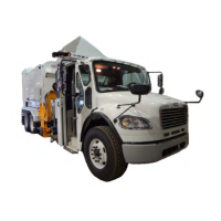
Figure 3-56
Pressure relieg valve (mid-inlet section)
4. Loosen the locknut and turn the screw clockwise as far as it will go. Note the starting position.
5. Run a hydraulic function and note the reading on the gauge. This reading should be
approximately 2350 psi and indicates the pressure relief setting of the
top inlet section. This should
be approximately 100 psi higher than the mid-inlet section.
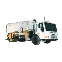
6. If adjustment is required (pressure is higher or lower than 2350 psi), loosen the locknut of the top
inlet section pressure relief valve and turn the screw clockwise to increase the pressure,
counterclockwise to decrease (see Figure 3-57).
Figure 3-57
Pressure relief valve (top inlect section)
7. Repeat the operation of the hydraulic function and check the pressure is at 2350 psi. Tighten the
locknut.
8. Now return the mid inlet section pressure relief valve screw to the starting position noted in step 4
and check that the main system pressure is at 2250 psi (see Figure 3-56).
9. If adjustment is required, turn the screw clockwise to increase system pressure, counterclockwise
to decrease.
10. Repeat the operation of the hydraulic function and check the pressure is at 2250 psi. Tighten the
locknut and recheck.
11. Remove the gauge and replace the plug.
Adjusting the Pressure Switch
Both the commercial and residential Front Loaders are equipped with a pressure switch set to
2150 psi. Refer to “Pressure Switch” on page 100.
 Loading...