3) Take 50 pin ribbon connector, with mounting
plate
attached, and
secure
it
in Interface opening, 54 (after any existing
plate
is
removed). Place 14 pin header connector into board connector JF
(noting Pin
1
to Pin
1
alignment).
Note: Ribbon cable and
14
pin header
are
only present for
BCD
option.
4) If
set
point
is
to be controlled externally, main circuit board
jumpers JMP1 and JMP2 must be cut.
Connect black (or green) and white
wires
of
BCD/L-A
board to
7
pin
rear
panel connector
53.
White goes to pin
C
and black (or
green) goes to pin
D.
6) Replace instrument cover.
5)
3.11 Installation of
DRC
IEEE
Option Board
The installation of the
DRC
IEEE
option board can be done
as
follows
:
1)
Remove instrument cover.
2)
3) Install 14 pin header into connector
JF.
Install 24 pin header
Remove blank plate covering J4 connector on
rear
panel.
into
JD'.
Note pin
1
to pin
1
correlation. (See Figure 6.5
-
DRC-84C Component Layout for connector locations).
4)
Place
option board in J4 opening and secure in place with screws
provided.
5)
Replace instrument cover.
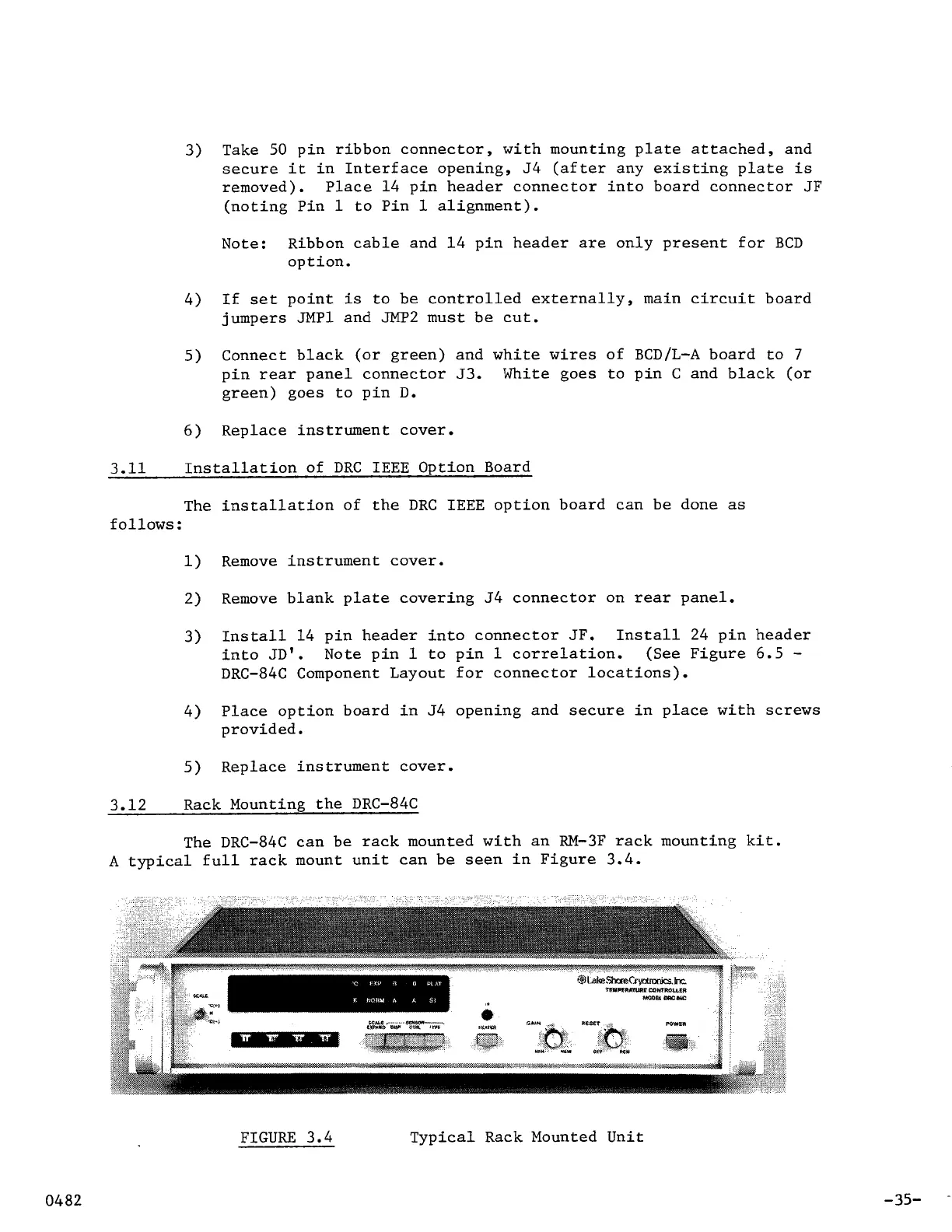
3.12 Rack Mounting the DRC-84C
The DRC-84C can be rack mounted with an RM-3F rack mounting kit.
A
typical full rack mount unit can be
seen
in Figure 3.4.
FIGURE
3.4 Typical Rack Mounted Unit
-35-