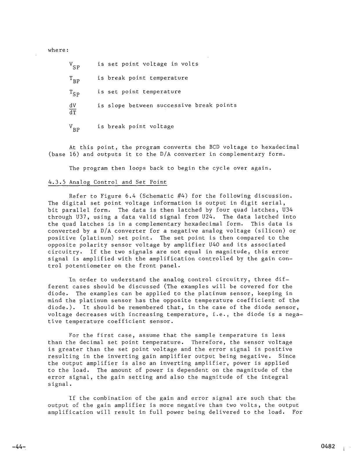
where
:
is set point voltage in volts
is break point temperature
is set point temperature
SP
V
TBP
TSP
dV is slope between successive break points
dT
VBP
is break point voltage
At this point, the program converts the BCD voltage to hexadecimal
(base
16)
and outputs it to the D/A converter in complementary form.
The program then loops back to begin the cycle over again.
4.3.5
Analog Control and Set Point
Refer to Figure
6.4
(Schematic
#4)
for the following discussion.
The digital set point voltage information is output in digit serial,
bit parallel form. The data is then latched by four quad latches,
U34
through
U37,
using a data valid signal from
U24.
The data latched into
the quad latches is in a complementary hexadecimal form. This data is
converted by a D/A converter for a negative analog voltage (silicon) or
positive (platinum) set point. The set point is then compared to the
opposite polarity sensor voltage by amplifier
U40
and its associated
circuitry. If the two signals are not equal in magnitude, this error
signal is amplified with the amplification controlled by the gain
con-
trol potentiometer on the front panel.
In
order to understand the analog control circuitry, three dif-
ferent cases should be discussed (The examples
will
be covered for the
diode. The examples can be applied to the platinum sensor, keeping in
mind the platinum sensor has the opposite temperature coefficient of the
diode.).
It
should be remembered that,
in
the case of the diode sensor,
voltage decreases with increasing temperature, i.e., the diode is a nega-
tive temperature coefficient sensor.
For the first case, assume that the sample temperature is less
than the decimal set point temperature. Therefore, the sensor voltage
is greater than the set point voltage and the error signal is positive
resulting in the inverting gain amplifier output being negative. Since
the output amplifier is also an inverting amplifier, power is applied
to the load. The amount of power is dependent
on
the magnitude of the
error signal, the gain setting and also the magnitude of the integral
signal
.
If the combination of the gain and error signal are such that the
output of the gain amplifier is more negative than two volts, the output
amplification will result in full power being delivered to the load. For
-44-


 To Next Page