PAGE 5
HEX (JAM) NUT
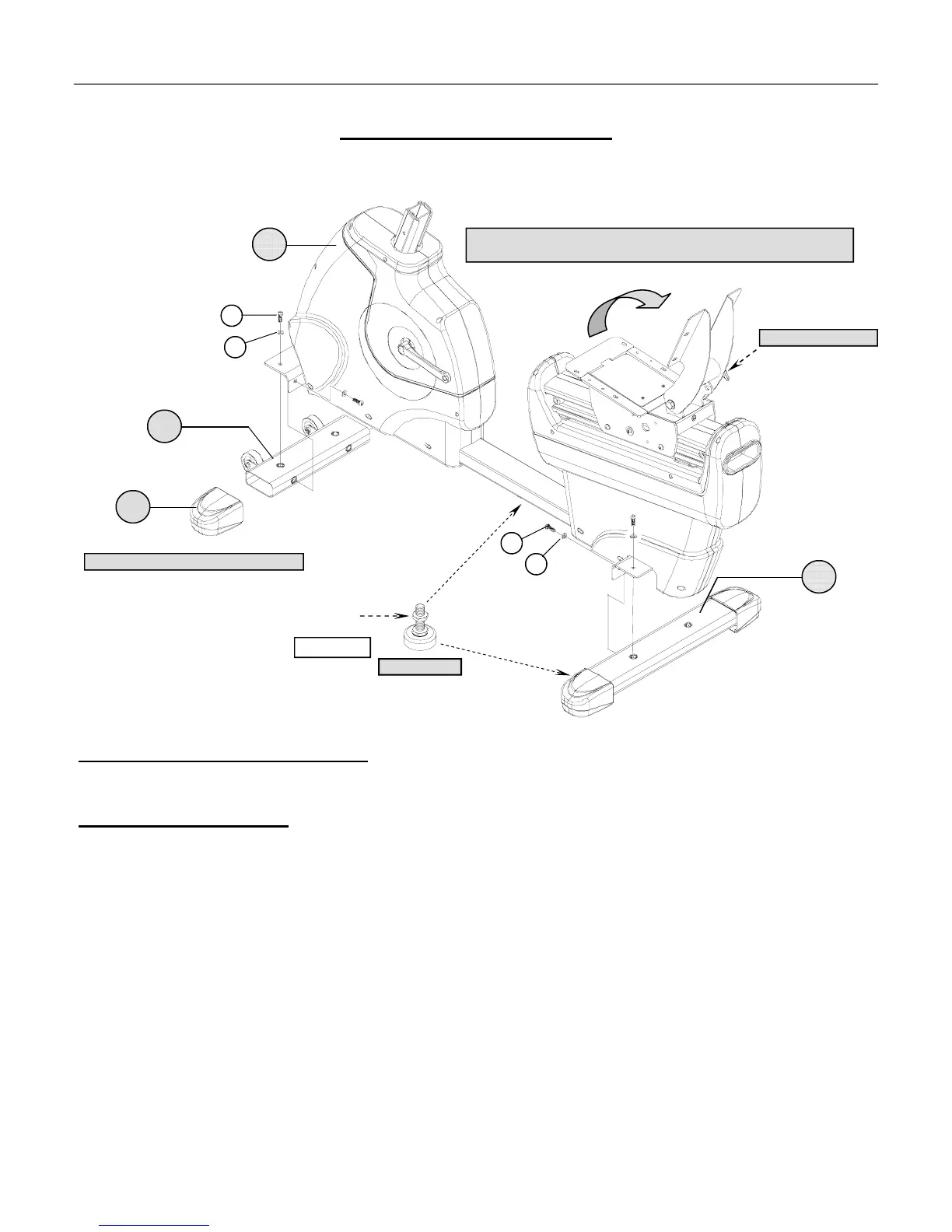
ASSEMBLY STAGE #1
Attach Stabilizer Assemblies
Assembly Hardware Required:
#24 Cap Screws Qty. 8 #27 Flat Washers Qty. 8
Assembly Description:
A) Securely fasten the Front Stabilizer Assembly (#2) to the Base Assembly (#1) using 4-Cap Screws (#24) and
4–Flat Washers (#27). One set of hardware will mount from the top and the other set will mount from the inside
frame flange. Assembly Note: The transport wheels should be facing outward..
B) From the side; tip the unit up a slight angle and slide an End Cap (#3) over each end of the Front Stabilizer
Assembly (#2).
C) Securely fasten the Rear Stabilizer Assembly (#4) to the back of the Base Assembly (#1) using 4- Cap Screws
(#24), 2–Flat Washers (#27). One set of hardware will mount from the top and the other set will mount from the
inside frame flange.
Important: Adjust the Levelers (#30) on bottom the Rear Stabilizer Assembly (#3) and the underside of the middle
frame area to keep the bike from rocking on an uneven surface. Once the correct adjustment is made, tighten the Hex
(Jam) Nuts flush against the frame surface. (Reference FIGURE 1).
♦ Assembly Stage #1 completed
A
SSEMBLY INSTRUCTION
24
24
27
4
1
#30 LEVELER
2
FIGURE #1
TRANSPORT WHEELS FACE OUTWARD
3
27
MOVE THE BACK PAD SUPPORT TO A VERTICAL POSITION AND USE THE
T-
HANDLE POP-PIN TO LOCK IT IN PLACE.
T-HANDLE POP-PIN