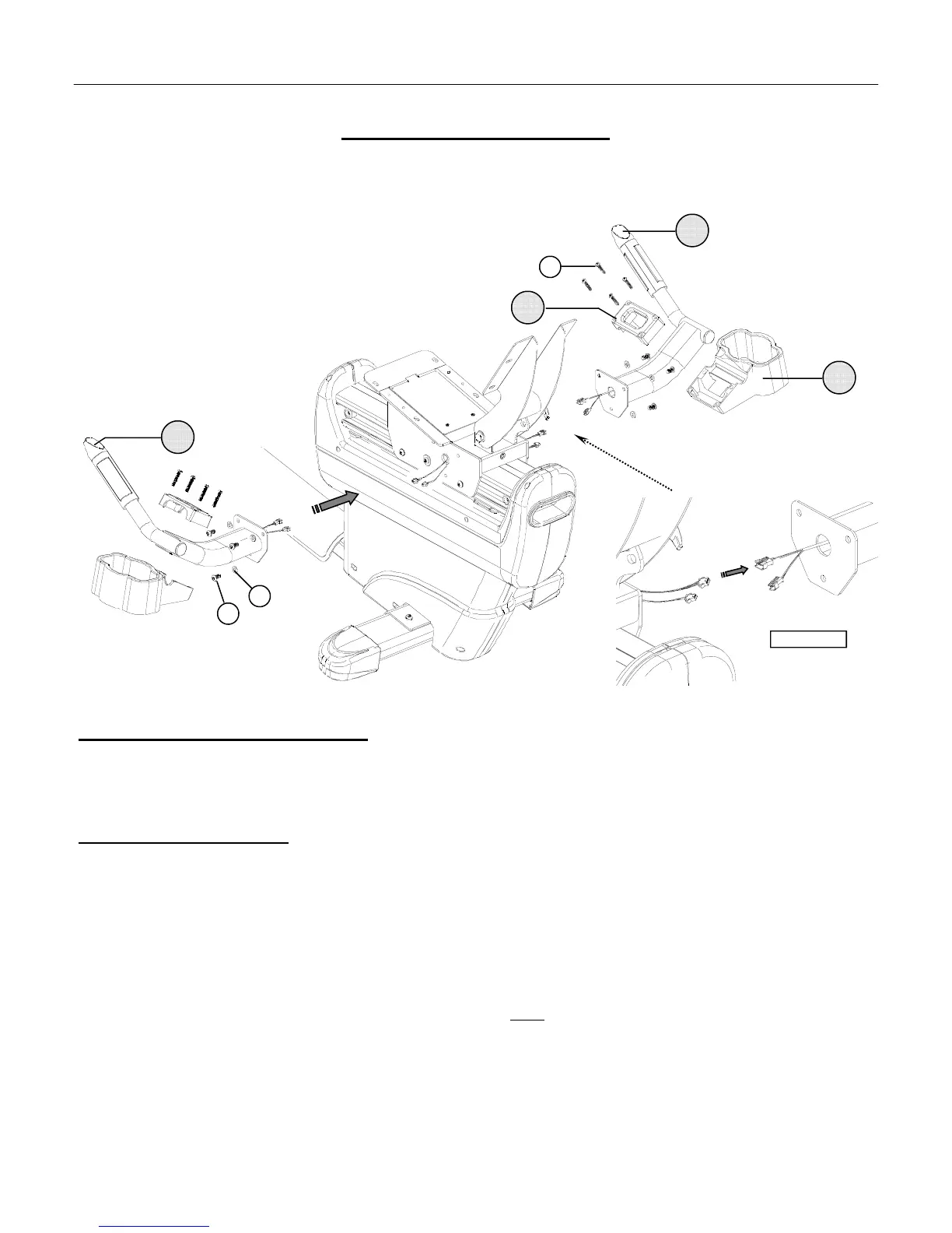
ASSEMBLY STAGE #3
Attach Handle Assemblies
Assembly Hardware Required:
#22 Cap Screws Qty. 6 #27 Flat Washers Qty. 6
#25 Phillips Screws Qty. 8
Assembly Description:
A) Plug the connectors coming from the Seat Slider Assembly into the corresponding cable receptacles of the Right
Handle Assembly (#8) (Reference FIGURE #2 ). Tuck away the excess cable length and mount the Handle
Assembly to the Seat Slider frame using 3-Cap Screws (#22) and 3-Flat Washers (#27).
B)
Plug the connectors coming from the Seat Slider Assembly into the corresponding cable receptacles of the Left
Handle Assembly (#7) (Reference FIGURE #2 ). Tuck away the excess cable length and mount the Handle
Assembly to the Seat Slider frame using 3-Cap Screws (#22) and 3-Flat Washers (#27).
C)
Fit the 1-Bottle Tray (#10) and 1-Mounting Clamp (#9) on each handle assembly and secure the parts together
using 4-Phillips Head Screws (#25).
Note: Use the handle / lever (not shown) positioned on the right side of the Seat Slider Assembly to adjust the seat frame
position. Pulling up on the lever, releases the locking mechanism. Once an adjustment is made, release the handle and the
seat frame will lock into a set position.
♦ Assembly Stage #3 completed
ASSEMBLY INSTRUCTION PAGE 7
FIGURE #2
22
27
9
7
10
8
25