3 OPERATING INSTRUCTIONS
The EMS power supply could be operated in several different configurations. Section 3
gives a detailed description of configuring the supply to the desired application.
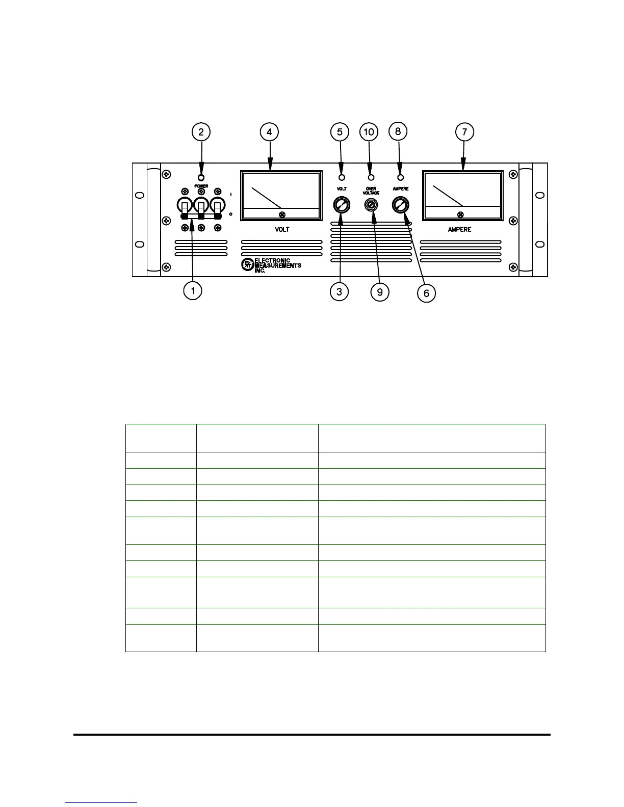
Figure 3.1: Front Panel, (5KW model shown)
3.1 FRONT PANEL
The following table provides a listing of the controls and indicators that are located on the
front panel along with a brief description of their functions. Figure 3.1 shows the location of
each control and indicator.
When glowing indicates that the output of the
supply has exceeded the Overvoltage trip level
OVP LED 10
Sets Overvoltage trip levelOVP Adjust9
When glowing indicates that the supply is in the
constant current mode
Current LED8
Displays output current of power supplyAmmeter7
Adjusts the output current from zero to full scaleCurrent Control6
When glowing indicates that the supply is in the
constant voltage mode
Voltage LED5
Displays output voltage of power supplyVoltmeter4
Adjusts the output voltage from zero to full scaleVoltage Control 3
When glowing indicates that the supply is onPower On LED2
Connects and disconnects AC input to supplyCircuit Breaker 1
FUNCTIONCONTROL/INDICATORREFERENCE
NO.
Table 3.1: Front Panel Controls and LEDs
83-473-000 Revision J
3 - 1 Operating Instructions