Vega Customer Applications Manual Section 3 - Analogue Secondary options
Rev. A3: October 2003 Page 12 of 48
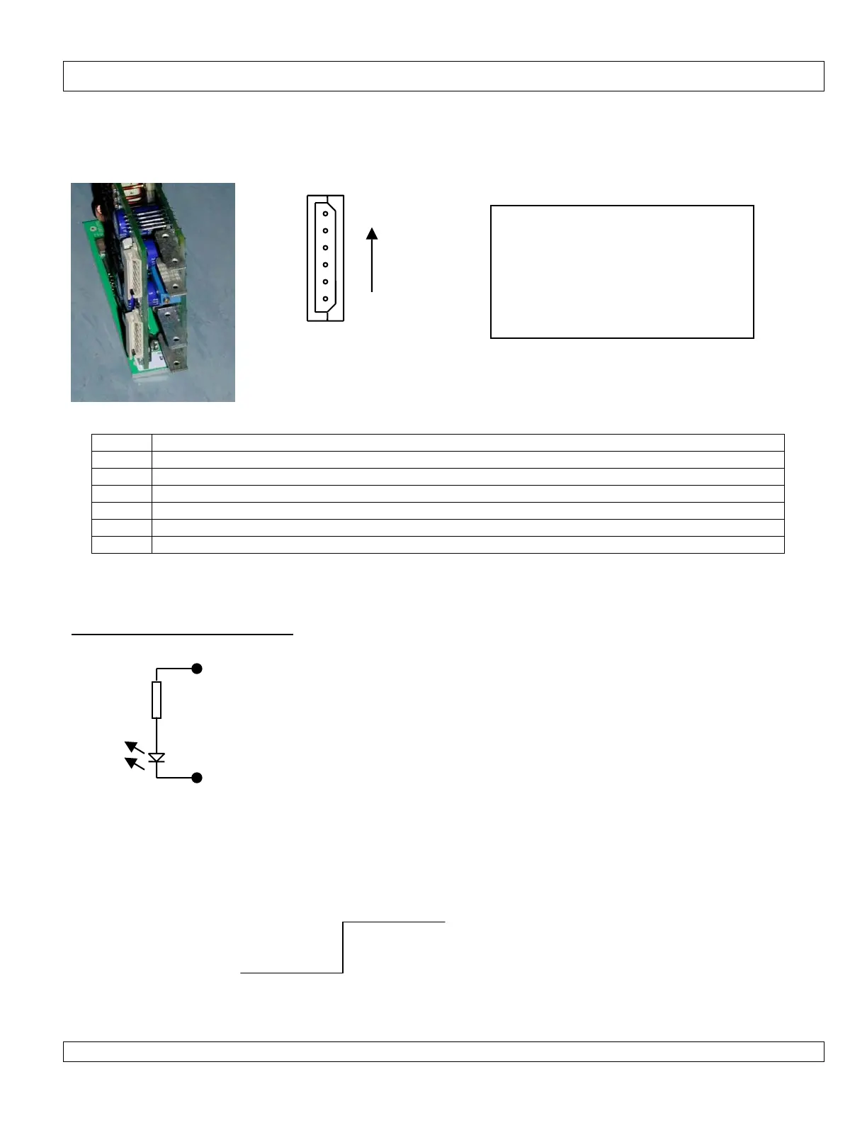
N option for TWIN (2 output) modules.
There is one 6 pin connector for EACH output. The connector for that output is directly adjacent to the faston output
terminals for that output.
Pin No Function
1 Module inhibit -Ve
2 Module inhibit +Ve
3 Module Good E
4 Module Good C
5 -Ve sense. *1
6 +Ve sense. *1
Note *1 : option board +ve sense and module +ve sense (2pin molex) are internally connected.
Module Inhibit circuit connection
When a module is inhibited, there may be up to 0.6V remaining at the outputs of the module.
Mating connector information:
Note: housing and pins supplied with
each power supply.
Housing: Molex 50-37-5063
Crimp pin: Molex 08-70-1039
Hand Crimp Tool: 11-26-0167 (Japan)
Or 11-01-0194(Europe or USA)
PIN 6
PIN 1
Viewed from rear of PSU
0 – 0.8V
2 – 5V
OUTPUTS ON OUTPUTS OFF
Module inhibit +Ve
390R
Module inhibit -Ve
Internal to the module inhibit is a 390ohm 1/8W resistor
and the diode of an opto-coupler.
To INHIBIT the module apply 2-5V between +ve and -ve.
Do not apply >6V or damage may result, although higher
voltages may be used to drive the circuit in which case
additional series resistor should be used to limit the
current. A current of 1-10mA will inhibit the module.