Do you have a question about the Lambda Vega Series and is the answer not in the manual?
Details on connecting the AC input supply to the Vega power supply.
Explains the function and connection of the remote sense feature.
Describes analogue primary options providing inhibit, enable, and auxiliary supply functions.
Introduces Option N for module good signal, module inhibit, and starpoint paralleling.
Describes redundant and hot-swap configurations for system reliability.
Explains the method for measuring ripple and noise using an oscilloscope.
Guides on proper installation for optimal airflow and thermal management.
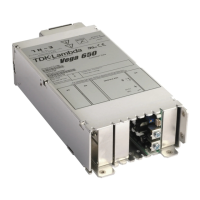
Provides dimensional drawings and fixing details for the Vega 650 Customer Air model.
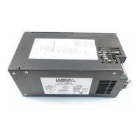
Displays outline drawings and dimensions for the Vega 650 Screw Terminal Input model.
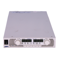
Shows outline drawings and dimensions for the Vega 650 Faston Input model.
Lists failure rates for various assemblies at different ambient temperatures.
Guides on installation practices to enhance EMC performance.
Explains the operation of the primary converter, including PFC and protection.
Describes the two levels of overvoltage protection in Vega output modules.
Explains how modules can be combined in series for increased voltage or current.
Lists common series combinations and their resulting voltage/current specifications.
Introduces the W2 module with voltage/current programming and inhibit/enable options.
Describes the W5 module with a wider voltage range and current capability.
| Input Voltage | 100-240Vac |
|---|---|
| Output Voltage | +3.3V, +5V, +12V, -12V, +5Vsb |
| Form Factor | ATX |
| MTBF | 100, 000 Hours |
| Protections | OVP, UVP, OPP, SCP, OCP, OTP |
| Operating Temperature | 0°C to 50°C |
| Safety Standards | CE, CB, TUV, FCC, UL |
| EPS Connectors | 4+4 pin |
| Output Power | 850W |
| Wattage | 850W |