Home
Lamtec
Control Unit
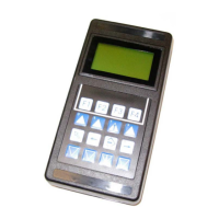
ETAMATIC S
Lamtec ETAMATIC S - User Manual
152 pages
Manual
Specs
Ask a question
Save Page as PDF
To Next Page
To Next Page
Loading...
www.lamtec.de
Sensors and Systems for Combustion Technology
Manual
ET
AMA
TIC / ET
AMA
TIC S
2
Table of Contents
Main Page
Default Chapter
3
Table of Contents
3
1 General Information
7
Validity of These Instructions
7
Variants - Device Configuration
8
2 Safety
10
For Your Safety
10
Associated Automatic Flame Guard
11
3 Brief Description
12
Display and Operational Controls
13
4 Operating Description
14
Starting with Pilot Burner
14
Starting Without Pilot Burner
14
5 Commissioning
15
Before Commissioning
15
Basic Settings
15
Password Entry
15
How to Change the Password
15
Edit Parameter
16
Select Language
16
Character of the Output Channels
17
Start with or Without Pilot Burner
19
Pre-Purge Period
21
Recirculation Delay
21
Deactivate Firing Rate Control Unit
22
Running Time of the Regular Firing Rate Input with TPS-Input
22
Minimum Running Time of the Fuel/Air Ratio Control
23
Post-Purge Time
23
Delaytime of the Air Dampers During Pre-Purge
23
Parameters of the Interface
24
Deactivate Leakage Test
25
Set Pilot Burner (Maintenance Mode)
26
Automatic Restart after Failure
26
Burner Firing Rate Controller
27
Enter Set Point Values
27
Control Range
28
Setting the Control Thermostat
29
Controller Parameters
29
Outside Temperature Limits
29
Display of the Units of the Burner Firing Rate Controller Values
30
Display Range in Bar
30
Setting
31
Setting the Limit Switches of the Motors
31
Adjusting Control Elements
31
Enter the Curve
31
Clear Memory
32
Programming the Ignition Point
32
Programming the Base Firing Rate
32
Programming the 3Rd up the 10Th Point
32
Saving Curve
33
Changing Points
33
Saving Changes
33
Re-Enter Range Limits
34
Fault
34
Reading Faults
34
Resetting Faults
34
Recalling Fault History
35
Calling up the Hour Counter
35
Calling the Checksums
36
6 Trim
37
What Happens if a Fault Occurs in the O Trim
37
How to Switch the Display
37
Air Deficiency Failure
37
Resetting O Errors
37
Calling Fault History O Trim
38
Automatic Function Monitoring During Operation
38
Test During Burner Start
38
O 2 Monitoring Band
39
O 2 Limit Curve
39
Dynamic Probe Test
40
Control Strategy
41
Connecting the O 2 Measurement Device
42
Operation and Display of the O2 Trim
43
Display and Interpretation of the Operating Modes
43
Calling up O 2 Trim Text Messages
44
Commissioning
44
Setting the Correction Range and the Correction Mode
44
Available Correction Modes
45
Correctiontype1
45
Correction Type 2
45
Setting the Correction Range
46
Calling up the Set Correction Mode
47
Checking the Combustion Limit Values
47
O 2 Curve Input
48
Changing O Setpoints
48
Manual Calculating and Setting of the Control Parameters
49
Guidelines
49
7 Internal Burner Firing Rate Controller
53
Purpose
53
Brief Description
53
Range Limits
53
Moving Screen "Actual Temperature Is too High
53
Enter Setpoint of Firing Rate Controller
54
Input Signals
54
Operating Description
55
Steam Pressure
55
Control by Atmospheric Condition
55
Setpoint Changeover
56
Start-Up Sequence
57
Thermostat and Control Range
58
Manual Control
60
Meaning of the Display
60
How to Adjust the Burner Firing Rate Controller
60
Control Range
61
Checking of the Safety Limiter
61
8 Control Mode
62
Aides for Setting
63
Valve Leakage Test
65
Valve Leakage Test Flow Chart
66
Calculation Example
66
Calculation of Gas Pressure Switching Point > Min
67
En13611:2012)
68
Standby
69
Standby Mode
69
Switching into Standby Mode Via LSB Module
71
9 Appendix
72
Mode Abbreviations Used
72
Flame Monitoring
73
Integral Flame Monitoring (Option)
73
Purpose
73
Characteristics Flame Sensor
73
Self Monitoring
74
General Information of the Optical Flame Monitoring
75
Optical Flame Sensors
75
Switching to Display the Flame Intensity
75
Avoiding EMC Effects
76
Fault Codes
77
Calling up the Condition of the Digital Inputs
99
Tips and Tricks
100
Set Pilot Burner
100
Post-Measurement of Safety Times
100
Process Sequence Charts
101
Connection Diagrams
109
Connection Examples Regular Firing Rate Input
111
Connections in Non Grounded Power Line Networks
112
Fan Force-Open During Fault
112
Connection Flame Scanner
113
Lamtec System Bus (Lsb)
115
Configuration of the Processor Board
115
LSB Connection
115
LAMTEC SYSTEM BUS Plug
118
Modem for Remote Control
120
Inernal Connecting Diagram of the Control Output Device
121
Interlock Chain Wiring Via 230 V
121
Valve Leakage Test Venting over the Roof
122
Switch- and Key Combinations
124
Sensor
125
Direct Connection to R. P. M. Sensor
125
Selection of a Suitable R. P. M. Sensor
128
Circuit Proposal 3-Wired Speed Sensor with Higher Power Supplay Voltage
130
External Switching of the Fuel Motors/ Valves
131
Feedback at Three-Point-Step Channels
133
Connect with Positive Locking
133
Fail-Safe Feedback
133
Examples of Potentiometers and Motors
133
Changing Control Drives / Potentiometers
135
How to Replace a Servo Motor
135
How to Replace a Potentiometer
135
Changing Eproms
135
Wiring Notes
137
Shields Connection
137
PE Busbar
137
Control Cabinet Wiring
138
Run to Shut-Off Limits
138
Tolerance Limit in Direction Air Deficiency
139
Example of a Protocol of the Parameter Settings of the Monitoring Bands
141
Technical Data
142
ETAMATIC Without Internal Flame Monitoring
145
Dimensions and Weight
146
Declaration of Conformity
150
Other manuals for Lamtec ETAMATIC S
Quick Reference
26 pages
Need help?
Do you have a question about the Lamtec ETAMATIC S and is the answer not in the manual?
Ask a question
Lamtec ETAMATIC S Specifications
Print Specification
General
Type
ETAMATIC S
Category
Control Unit
Ambient Temperature
-20°C to +60°C
Protection Class
IP20
Relative Humidity
5 to 95% non-condensing
Related product manuals
Lamtec ETAMATIC OEM
160 pages
Lamtec ETAMATIC S OEM
160 pages
Lamtec 663R0932
16 pages