54
4 Appendix
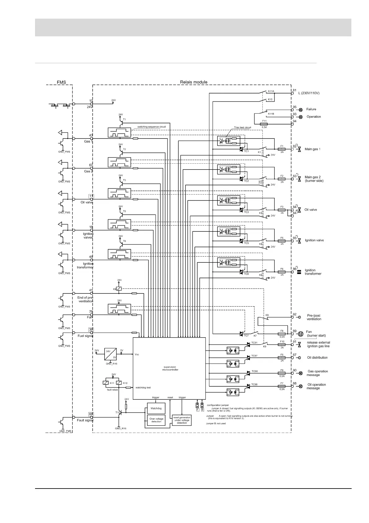
4.2.2 Block Diagram Type 660 R 0016
*) At terminals 82 through 86 an alternating testing current must flow. Otherwise the relay mod-
ule will switch off all outputs during the self-test which forces the FMS to do a fault-shutdown.
At a mains voltage of 230V an impedance of Z<=100kW is required. At 110V Z must be 22kW
or less. If necessary connect an appropriate auxiliary load (as a resistor or RC element). Out-
puts which are not switched on by the FMS (e.g. ignition valve when starting without ignition
burner) need no auxiliary load.