33
5 Commissioning
Space requirement for mounting and removal
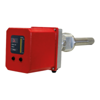
Fig. 5-3 LAMTEC GFI pilot burner space requirement for mounting and removal
For the insertion of the device, at least the full device length in axial extension of the outer tube
is to be kept clear. For maintenance and servicing, there must be the possibility of being able
to completely remove the device again.
Subsequently attached system components in the surrounding environment must be easily re-
movable.
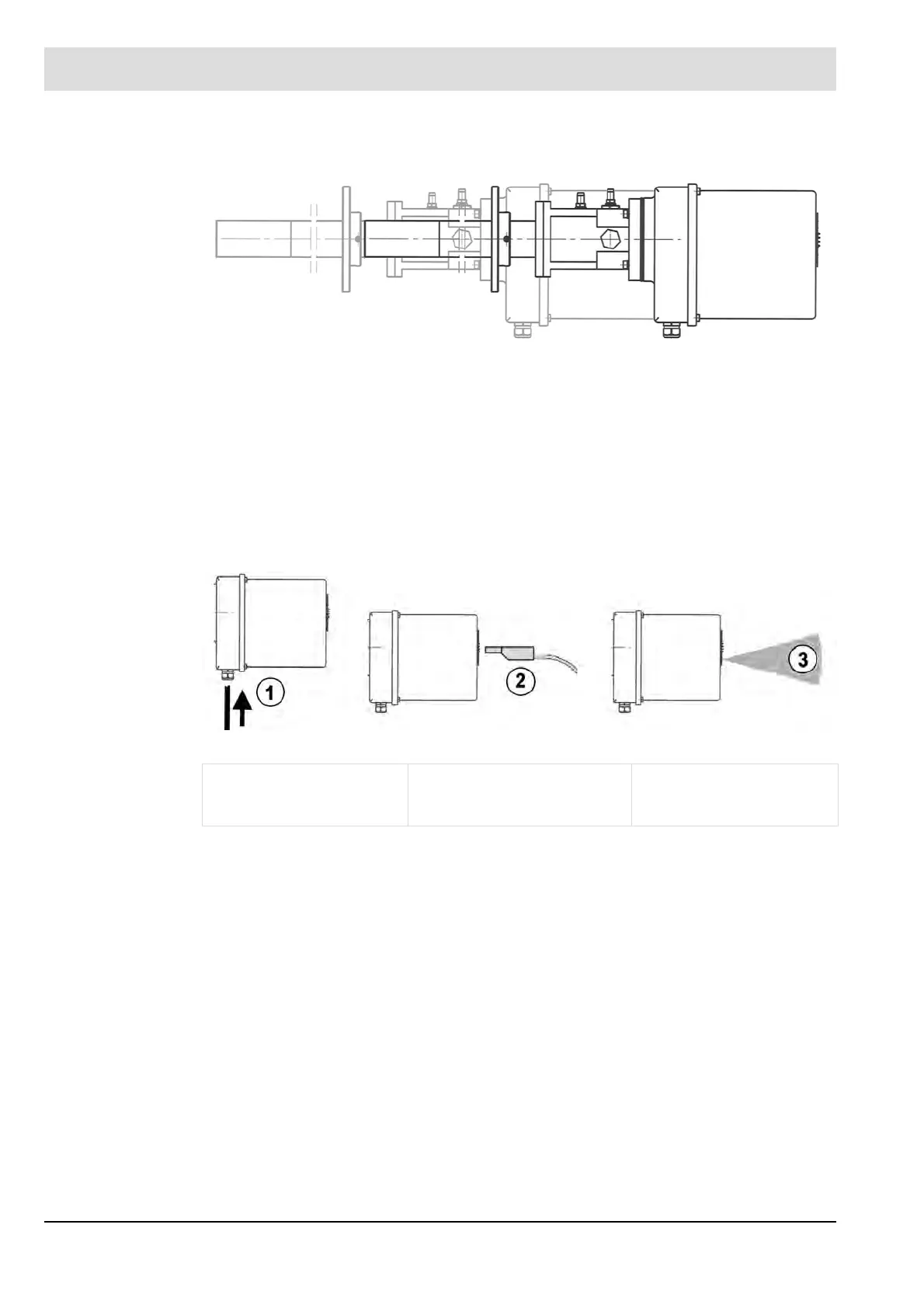
Remaining clearance after mounting
Care must be taken to ensure that the following clearance on the rear side of the device re-
mains clear at all times even after mounting:
Fig. 5-4 Remaining clearance after mounting the pilot burner
1 Space for
cable connection
2 Working space for
connecting of the
measurement device plugs
3 View area for the
detection of the
pilot lamp