82
10 Options
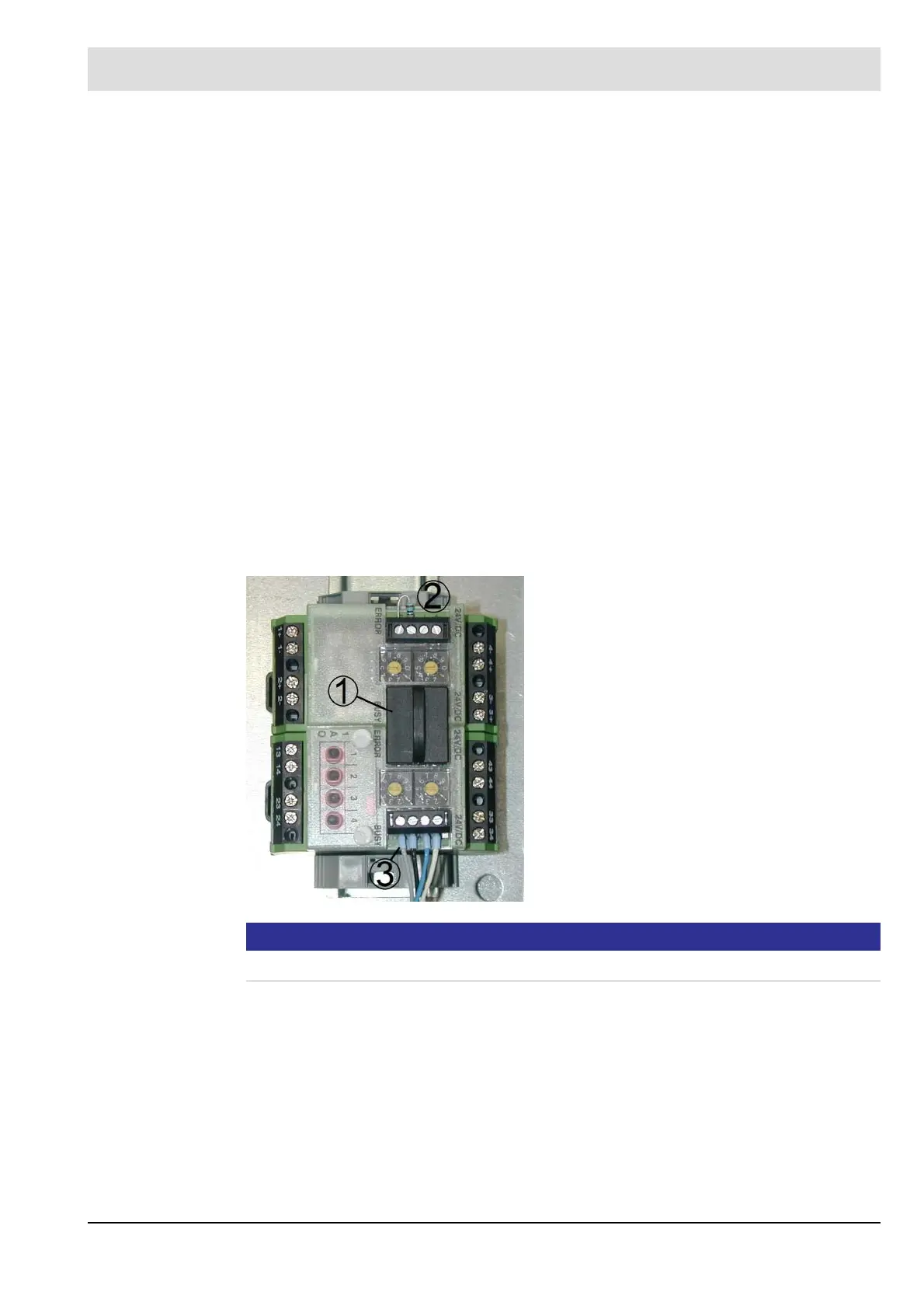
3. Connect the LSB module to the external voltage supply (24 VDC) and to LSB.
Term. 72/74 CAN-H
Term. 73/75 CAN-L
4. Set address at the module
LSB-Module with 4 analogue outputs, order no. 663R4025 or
663R4029 LSB-Module address 19
LSB-Module with 4 digital outputs, order no. 663R4027
LSB-Module address 03 for output 1 ... 4
LSB-Module address 51 for output 5 ... 8
LSB-Module with 4 digital inputs, order no. 663R4028
LSB-Module address 11 for input 1 … 4
LSB-Module address 55 for input 5 ... 8
HART-Module with 2 analogue outputs, order no. 657R5930 (not LT3-F)
Setting of the LSB-Module address not necessary
Efficiency-Module with 2 analogue in- and outputs, order no. 657R5940
Setting of the LSB-Module address not necessary
PROFIBUS DP-Module, order no. 657R5950 (not LT3-F)
Setting of the LSB-Module address not necessary
NOTICE
Max. line length between the lambda transmitter LT3-F and LSB modules = 500 m.
Recommendation for line lengths and line cross-sections of the LAMTEC SYSTEM
BUS:
•0 ... 40 m 2 x 2 x 0.34 mm
2
, cabled in pairs with screening, impedance 120
•40 ... 300 m 2 x 2 x 0.5 mm
2
, cabled in pairs with screening, impedance 120
• 300 ... 500 m 2 x 2 x 0.75 mm
2
, cabled in pairs with screening, impedance 120
Example cable type for fixed installation:
• LAPP cable 2170267 (LAMTEC article no.: 05L05 2 x 2 x 0.5)
• HELUKABEL 800685
1 Jumper plug
2 LSB terminal resistance 120
3 Connecting terminals for
- Power supply
- LAMTEC SYSTEM BUS