Do you have a question about the Landis+Gyr E470 Series and is the answer not in the manual?
Lists mandatory safety regulations for meter installation and handling.
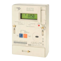
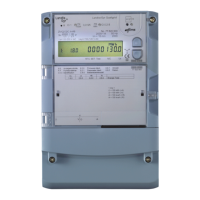
Details the meter's supply, switch, energy registers, and core features.
Lists technical specifications like accuracy, standards, voltage, power, dimensions, and interfaces.
Explains the code used to define the meter's hardware configuration.
Describes energy measurement capabilities and instantaneous values monitored.
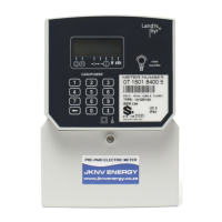
Describes the meter's operation in Credit and Prepayment modes.
Explains how load limit parameters control supply and register events.
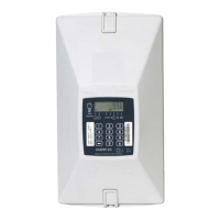
Describes the meter case, top, middle, and lower parts.
Explains the ICHI for attaching communication hubs and its specifications.
Details typical displays including time, total, rate, and instantaneous values.
Details various status displays when the meter is in credit mode.
Details supported prepayment displays and operational scenarios.
Details displays for payment-based and time-based debt collection.
Pre-installation checks like case integrity and seals.
Steps for correctly mounting the meter board and fixing points.
Details connecting phase/neutral wires and ALCS/ICHI.
Instructions for cutting, stripping, and inserting wires.
Steps to connect an ALCS to the meter's terminal block.
Procedure to connect the communications hub to the meter.
Steps to commission the meter and verify its functionality.
Procedure for joining the meter to the Home Area Network (HAN).
Recommended automated process for initial HAN joining.
Manual process for HAN join if automatic fails.
Step-by-step guide for HAN join and commissioning.
How to verify meter commissioning via Customer or Service Menu.
Lists security requirements met by the meter per SMETS2.
Details tamper protection measures like sealing and fraud detection.
Explains detection of cover removal, magnetic fields, and DC magnets.
Details how meter security credentials are produced and configured.
Lists default hardware configurations like accuracy, voltage, and current.
Details default software settings for display, PIN, and DST.
Sets meter operation to Credit or Prepayment mode.
Configures parameters for load limiting operation.
Describes the ON, OFF, and ARM states of the supply switch.
How users purchase credit and how it's delivered to the meter.
Defines emergency credit limit and availability threshold.
Supports payment-based and time-based debt collection methods.
Debt recovered as a percentage of payment top-ups.
Debt charged on a regular time basis with configurable periods.
Describes the integrated switch for connecting/disconnecting supply.
Details states like connected, disconnected, and armed with LCD indicators.
Describes manual reconnection via Normal or PIN protected processes.
Steps for normal reconnection via meter buttons.
Steps for reconnection when PIN protection is enabled.
Details the structure and process of entering the privacy PIN.
Explains the structure and process for enabling, changing, or disabling the PIN.
Explains the top-level display structure and navigation.
Shows the credit mode display and navigation flowchart.
Describes displays showing meter status like balance and supply.
Details the process of entering the PIN to access protected displays.
Explains how to access and manage the boost function.
Lists functions accessible via the customer menu.
Procedure to activate or deactivate the In-Service Test (IST) mode.
Disconnects or reconnects the meter to the HAN (ZigBee network).
Describes power failure detection and the power-down procedure initiation.
Details procedures initiated when supply voltage reaches nominal value.
Actions during power-up, including data restoration and event logging.
Steps for safe disconnection, including fuse removal and wire disconnection.
Procedures for meter repair, including labeling and packaging.
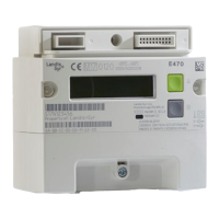
| Type | Electricity Meter |
|---|---|
| Display | LCD |
| Communication | Ethernet, GPRS |
| Frequency | 50 Hz / 60 Hz |
| Current | 10(100) A |
| Mounting | DIN Rail |
| Standards Compliance | IEC 62052-11, IEC 62053-21, IEC 62053-22, IEC 62053-23 |
| Weight | Varies depending on model. Consult product datasheet. |
| Voltage | 230/400 V |
| Phase | 1-phase, 3-phase |