N15039
A1+
~115V
~220V/~230V
T1.6A L 250V
T3.15A L 250V
(CH2)
230 V
0
1
7
8
10 1112
95 6
3
1 2
4
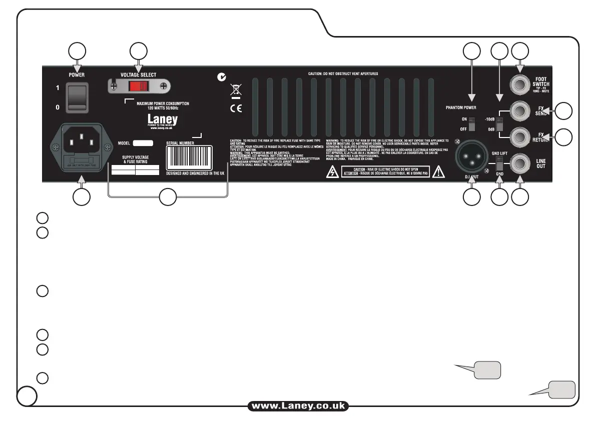
Mains Power Switch.
Power inlet socket. Connect to your power source. Make sure the specified voltage is correct for your country!
The main safety fuse for the unit is inside this drawer.
USE ONLY THE CORRECT SIZE AND RATING OF FUSE AS SPECIFIED ON THE PANEL.
Information area relating to the amplifier: Serial Number, Fuse Type & Rating etc
Voltage Selection Switch: This is factory set to the correct voltage for the region the product is supplied to. If
necessary it can be reset by removing the mains lead and then loosening (but not removing) the screws securing the
cover. The cover can then be pivoted away from the switch which can be moved to select the alternate voltage. DO
NOT reconnect the mains lead until the cover is replaced and secured. It is essential to ensure that the correct fuse is
fitted (as printed on the panel) for the voltage being used.
IMPORTANT:
Turns on a phantom power supply to Channel 2 (CH2), LED (22) on the front panel is lit when ON.
(IMPORTANT: Only use for Microphones requiring Phantom Power!)
Connect a Laney FS2 footswitch here, FX Mute (Tip) & Master Mute (Ring).
(FX Mute & Master Mute front panel switches must be enabled before they can be operated from the footswitch).
3
5
4
6
1
2
TIP
TIP
6
REAR PANEL CONTROLS