Do you have a question about the Laney LA65D and is the answer not in the manual?
Comprehensive safety guidelines for operating the electrical product, covering installation, usage, and maintenance.
Steps to follow after unpacking, including voltage check and cable connection guidance.
Lists key technical specifications including voltage, power rating, output, and features.
A letter from the CEO welcoming the user to the Laney family and highlighting brand heritage.
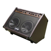
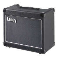
Describes the LA65D's transportable design, dual channels, digital effects, and drivers.
Includes MIC/AUX IN, GAIN, LO, HI, and REVERB settings for Channel 1.
Covers INSTRUMENT input, PAD switch, Channel 2 GAIN and EQ settings.
Features ANTI-FEEDBACK, PHASE switch, and PEAK LED indicator.
Controls for digital chorus, shimmer effect, and reverb for Channel 2.
Connects external audio sources and controls overall amplifier volume.
Power inlet socket and main power switch for unit operation.
Details the power fuse rating and displays model/serial number information.
Connects headphones and mutes internal speakers.
Balanced output for direct injection and ground link switch for hum reduction.
Connect external effects via send and return sockets.
Bypasses FX loop or selects 0dB/-10dB level.
Connects an optional footswitch for remote control of chorus/reverb.
Guidance on proper equipment connection, cable quality, and servicing procedures.
Details the amplifier's kickback style for stage monitor use and stability precautions.
Illustrates the internal signal path and architecture of the amplifier.
Information on CE, RoHS, and WEEE directives applicable to the product.
Diagrams showing common connection setups for instruments and audio sources.
Illustrates connections for headphones, mixer desks, and external FX controllers.
Provides visual examples of front panel settings for various sound configurations.
An empty section for users to record their own notes and settings.
Contains company contact information and a disclaimer regarding product specification changes.
| Power Output | 65W |
|---|---|
| Speaker Size | 12 inches |
| Channels | 2 |
| Type | Guitar Combo Amplifier |
| Technology | Solid State |
| Footswitch | Optional |
| Inputs | 1 x 1/4" |
| Effects | Reverb |
| Speakers | 1 x 12" |
| EQ | 3-band EQ |