12
Motherboard Information
Chapter 3
Network Application Platforms
The controller contains two modes of operation—a
legacy mode using I/O space, and an AHCI mode
using memory space. Software that uses legacy
mode will not have AHCI capabilities.
The AHCI ( Advanced Host Controller Interface) is a
programming interface which defines transactions
between the SATA controller and software and
enables advanced performance and usability with
SATA. Platforms supporting AHCI may take advantage
of performance features such as no master/slave
designation for SATA devices—each device is treated
as a master—and hardware assisted native command
queuing. AHCI also provides usability enhancements
such as Hot-Plug. Here is the list of the AHCI capabilities
which exist in the system:
Hardware assisted native command queuing1.
Aggressive power management2.
LED indicator support3.
Note: To configure your hard disk as AHCI
compatible, use the BIOS menu. Refer to IDE
Configuration Settings on Chapter 4 BIOS Settings.
Also, Intel(R) Matrix Storage Manager (for use on
systems using Intel(R) 82801HBM I/O Controller
Hub (ICH8M)- AHCI only) has to be installed, for
more information, visit http://downloadcenter.
intel.com/Detail_Desc.aspx?lang=eng&chan
geLang=true&DwnldId=19607
Serial Interface Connectors(J9): It is for connecting the
RS-232 serial port module cable. This is COM2 where
as the external console port (RJ45) is COM1.
SPI-ROM Update Connector (J3): Using the appropriate
cable to connect this 10-pin ISP pin header connector,
the user can update the SPI Flash soldered on board.
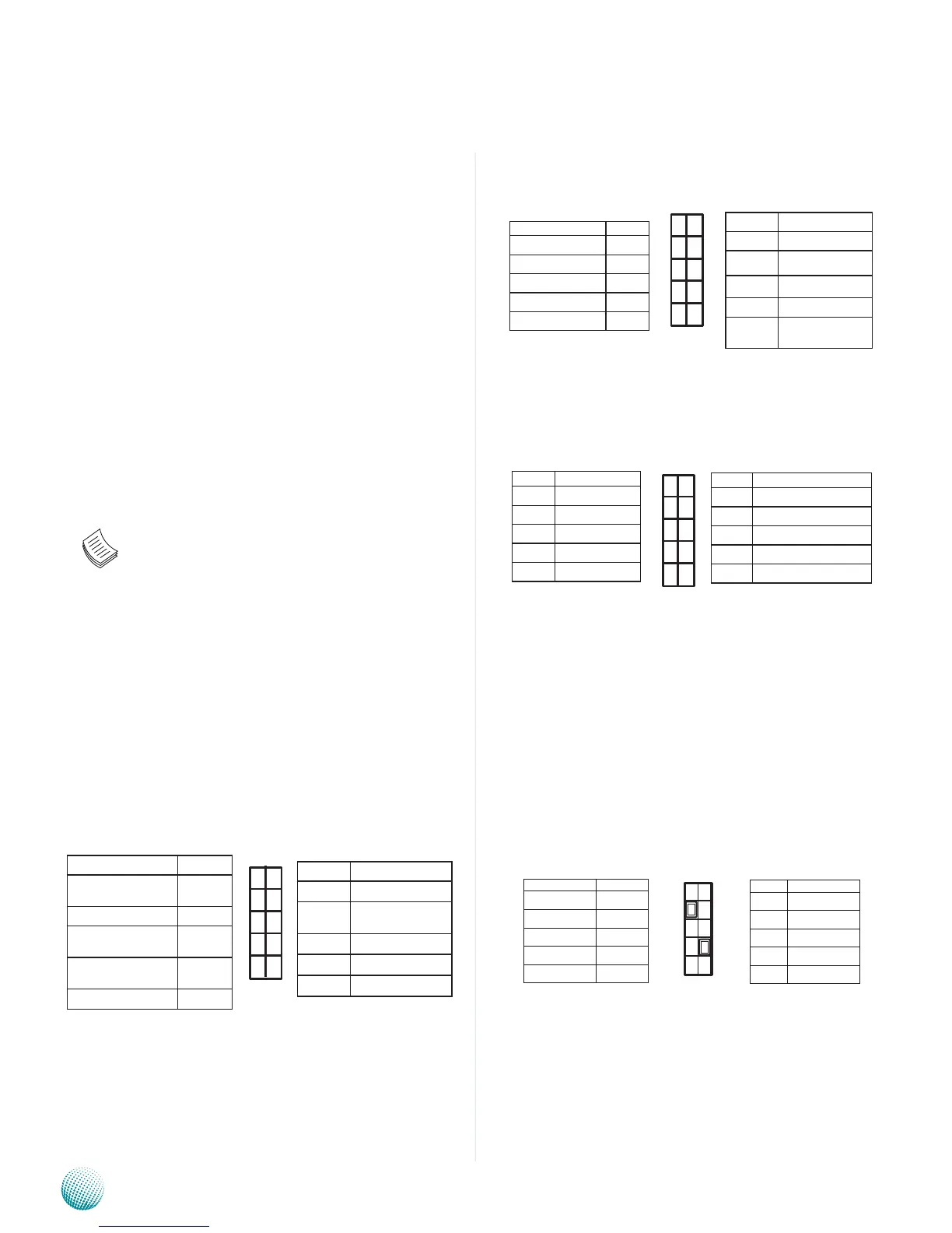
LPC I/O bus (Port 80 output for Debug Card) (J4):
It is Intel proprietary connector for connecting a
checkpoint device to output checkpoints throughout
bootblock and Power-On Self Test (POST) to indicate
the task the system is currently running.
SIM Card Tray (CN5): It is for connecting SIM card for
mobile Internet connection.
Mini-PCIe Socket(CN6): It is for connecting WiFi module
to serve Wireless LAN connections or connecting
Wireless 3G module for mobile Internet connections.
The socket is provided through the Universal Serial
Bus (USB) 2.0 host interface.
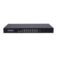
USB Connector(USB 2 and 3, J11) : It is for connecting
the USB module cable. It complies with USB2.0 and
is capable of low-speed, full-speed, and high-speed
which can support up to 480 Mbps connection
speed.
Function Pin No.
Data Carrier
Detected
1
Received Data 3
Transmitted
Data
5
Data Terminal
Ready
7
Signal Ground 9
Pin No. Function
2 Data Set Ready
4 Request to
Send
6 Clear to Send
8 Ring Indicator
10 Signal Ground
1
3
5
7
9
2
4
6
8
10
Pin No. Function
2 NC
4 V_3P3_SPI
6 SPI_HOLD0_L
8 SPI_ICH_CLK
10 SPI_ICH_
MOSI
Function Pin No.
NC 1
SPI_CS0 3
SPI_ICH_MISO 5
KEY 7
GND 9
2
4
6
8
10
1
3
5
7
9
Pin No. Function
9 LPC_AD2
7 LPC_AD3
5 LPC_FRAME_N
3 RST_80DGPT_N
1 CLK_33M_P80
Pin No. Function
10 GND
8 GND
6 +3.3V
4 LPC_LAD0
2 LPC_LAD1
10
8
6
4
2
9
7
5
3
1
1
3
5
7
9
2
4
6
8
10
Function Pin No.
USB_VCC 1
Key 3
USBD0- 5
USBD0+ 7
Ground 9
Pin No. Function
2 Ground
4 USBD1+
6 USBD1-
8 Key
10 USB_VCC