41
Programming LAN Bypass
Appendix D
Network Application Platforms
Appendix D:
Programming LAN Bypass
The bypass function is used to link two independent
Ethernet ports when the system crash or powers off.
This means if your system is equipped with a LAN Bypass
function, a condition in your system will not interrupt your
network traffic. There are typically two communication
statuses for the bypass function, one is “Normal” status and
another is “Bypass” status. Lanner provides the following
methods for enabling the LAN Bypass function:
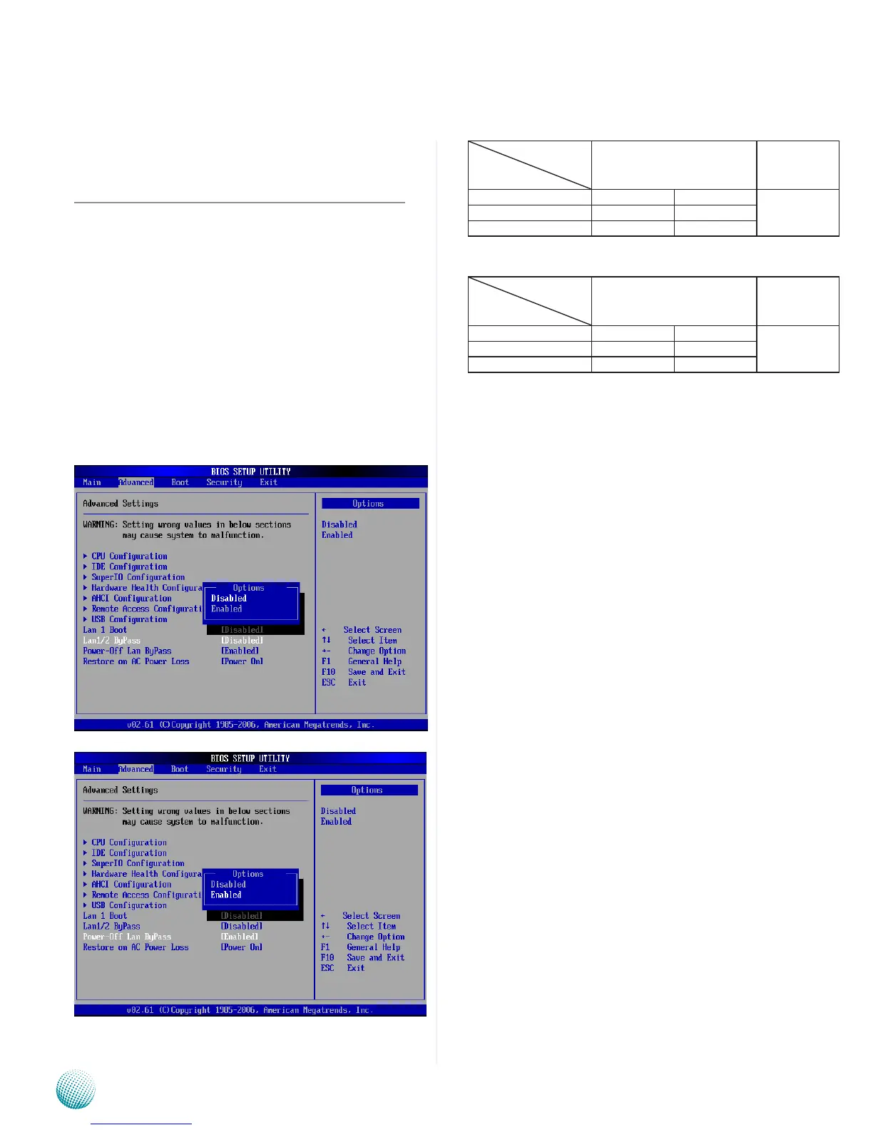
The Lan bypass can be turned on or off in two system 1.
states, i.e., power on and power off. The following are
the BIOS menu and illustration of the possibilities
of LAN bypass configuration with respect to both
power-on and power-off states.
Bypass settings
System Status
LAN Bypass for Port1 and
Port 2
LAN Bypass
1&2 when
power o
Enabled Disabled Enabled
PWR ON Bypass Non-Bypass
PWR OFF Bypass Bypass
Bypass settings
System Status
LAN Bypass for Port1 and
Port 2
LAN Bypass
1&2 when
power o
Enabled Disabled Disabled
PWR ON Non-Bypass Non-Bypass
PWR OFF Non-Bypass Non-Bypass
A watchdog timer can be used to control the LAN
2.
Bypass function dynamically by programming. Lanner
also provides sample code for bypass control with
WDT via programming. For sample code, look in the
LAN_Bypass_Watchdog directory under Driver and
Manual CD.
To compile:
#gcc wdbp.c -o wdbp
then switch to a root account to run ./wdbp for
excution:
#./wdbp
Commands:
Enable the bypass
#wdbp.exe –f
Set Watchdog Timer. This command will set the time
interval at which the counter will start count down.
#wdbp.exe -wl xxx (xxx: 1-255 sec for timer count
down)
Reset Watchdog Timer. This command will reset the
watchdog timer’s counter and the bypass status to
non-bypass.
#wdbp.exe -wr xxx (xxx: 1-255 sec for timer count
down)
For a description of the physical LAN ports equipped with
this functionality, refer to Front Panel Features in Chapter 1
Introduction.