- 11 -
POWER MODULES
Power Modules comes in a variety of configurations and sizes. The testing procedures described below illus-
trates the the set-up for a Dual Thyristor Bridge. The principle is the same for Thyristor/Diode, Diode/Diode,
and single Diode or Thyristor Modules.
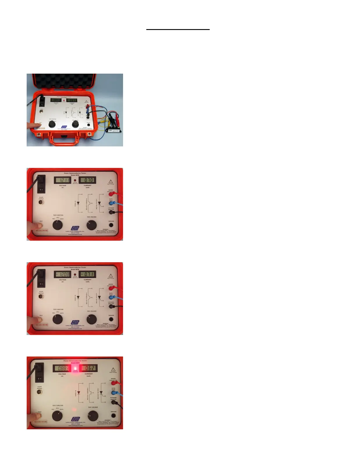
Make sure the Voltage Control is at the zero position (fully counter
clockwise) before turning the unit on. Connect the Anode, Gate and Cathode
leads to the device to be tested. DO NOT MIX UP THE ANODE AND
CATHODE LEADS OR HIGH VOLTAGE WILL BE APPLIED TO
THE GATE!
Place the function switch in the PRV position and press the “TEST” button.
Slowly increase the voltage while observing the Peak Voltage and Peak
Leakage Current on the panel meters.
In a properly functioning device, the rated voltage should be reached before
the current starts to rise rapidly, (the “break-over point”).
Place the function switch in the PFV position and repeat procedure described
above.
Place the function switch in the GATE position and slowly raise the Voltage
Control while observing the “TRIGGER INDICATION” light.
If the light does not turn on, the Gate on the SCR is faulty, and the device
should be replaced.