- 12 -
Transistor Modules
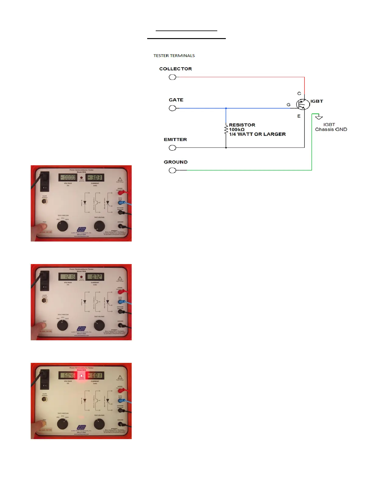
(IGBTs and Darlingtons)
•Connect test lead between the Ground
Plate of the component and the
GROUND terminal on the tester.
•Connect a 100k ohm Resistor between
the BASE and EMITTER terminals on
the tester.
•Do Not Mix Up the COLLECTOR and
EMITTER Leads or HIGH
VOLTAGE will be Applied to the
BASE!
•Connect the leads in the following order
to prevent shorting the device:
Ground, Emitter, Base, Collector.
Place the function switch in the PRV position and press the “TEST” button.
Slowly increase the voltage while observing the Peak Voltage and Peak
Leakage Current on the panel meters.
In most transistor modules, the current will rise immediately due to the
circuit design.
Place the function switch in the PFV position and press the “TEST” button.
Slowly increase the voltage while observing the Peak Voltage and Peak
Leakage Current on the panel meters.
In a properly functioning device, the rated voltage should be reached before
the current starts to rise rapidly, (the “break-over point”).
Place the function switch in the BASE position and slowly increase the
voltage while observing the “TRIGGER INDICATION” light.
If the light does not turn on, the Base is faulty, and the device should be
replaced.
Note: Typical turn-on voltage is 5-6 V. The current is so low in transistor
base circuit, that it will not show on the current meter.
Disconnect the leads in the following order to prevent shorting the device:
Collector, Base, Emitter, Ground