- 8 -
TESTING SET-UP AND PROCEDURES
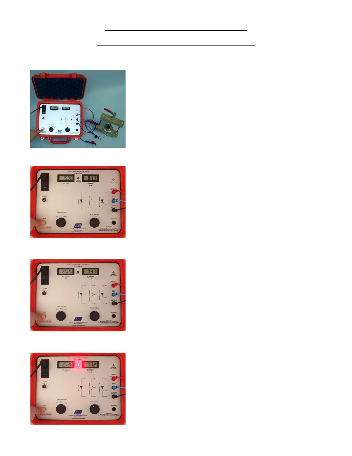
PRESSURE PACK (Hockey Puck) SCRs (Thyristors)
Make sure the Voltage Control is at the zero position (fully counter
clockwise) before turning the unit on. Connect the Anode, Gate and
Cathode leads to the device to be tested. DO NOT MIX UP THE
ANODE AND CATHODE LEADS OR HIGH VOLTAGE WILL BE
APPLIED TO THE GATE!
Place the function switch in the PRV position and press the “TEST”
button.
Slowly increase the voltage while observing the Peak Voltage and Peak
Leakage Current on the panel meters.
In a properly functioning device, the rated voltage should be reached
before the current starts to rise rapidly, (the “break-over point”).
Place the function switch in the PFV position and repeat procedure
described above.
Place the function switch in the GATE position and slowly raise the
Voltage Control while observing the “TRIGGER INDICATION” light.
If the light does not turn on, the Gate on the SCR is faulty, and the device
should be replaced.