Checking And Adjusting Calibration
6. Remove the black rubber plug from the X-axis calibration port. Using
a 3/32" hex driver, adjust the X-axis calibration. Turning the screw
clockwise will raise the beam in the +X axis (see pg 2). One full turn of
the screw will make approximately a 3/4"(19mm) change at 100'(30m)
turn the screw only as much as it will take to correct any error
observed in step 5. After making the adjustment, remove the laser from
the platform and give it two vertical shakes to center the compensator.
Adjusting calibration pushes on the pendulum of the compensator and
can cause it to take a set. The shaking procedure will relieve any set
that may have occurred. After shaking, place the laser on the platform
and re-check the X-axis calibration. Make any further adjustments
following the above procedure.
7. Rotate the laser 90 degrees to aim the +Y-axis (control panel) at the
target. Re-center the bubble. Check the reading at the target. If the
reading is on, or within tolerance of the true level mark, calibration is
complete. If not, continue on.
8. Remove the black rubber plug from the Y-axis calibration port. Using
a 3/32" hex driver, adjust the Y-axis calibration. Turning the screw
clockwise will raise the beam in the +Y-axis (see pg. 2). One full turn of
the screw will make approximately a 3/4"(19mm) change at 100'(30m)
turn the screw only as much as it will take to correct any error
observed in step 7. After making the adjustment, remove the laser from
the platform and give it two vertical shakes to center the compensator.
Adjusting calibration pushes on the pendulum of the compensator and
can cause it to take a set. The shaking procedure will relieve any set
that may have occurred. After shaking, place the laser on the platform
and re-check the Y-axis calibration. Make any further adjustments
following the above procedure.
Calibration is now complete.
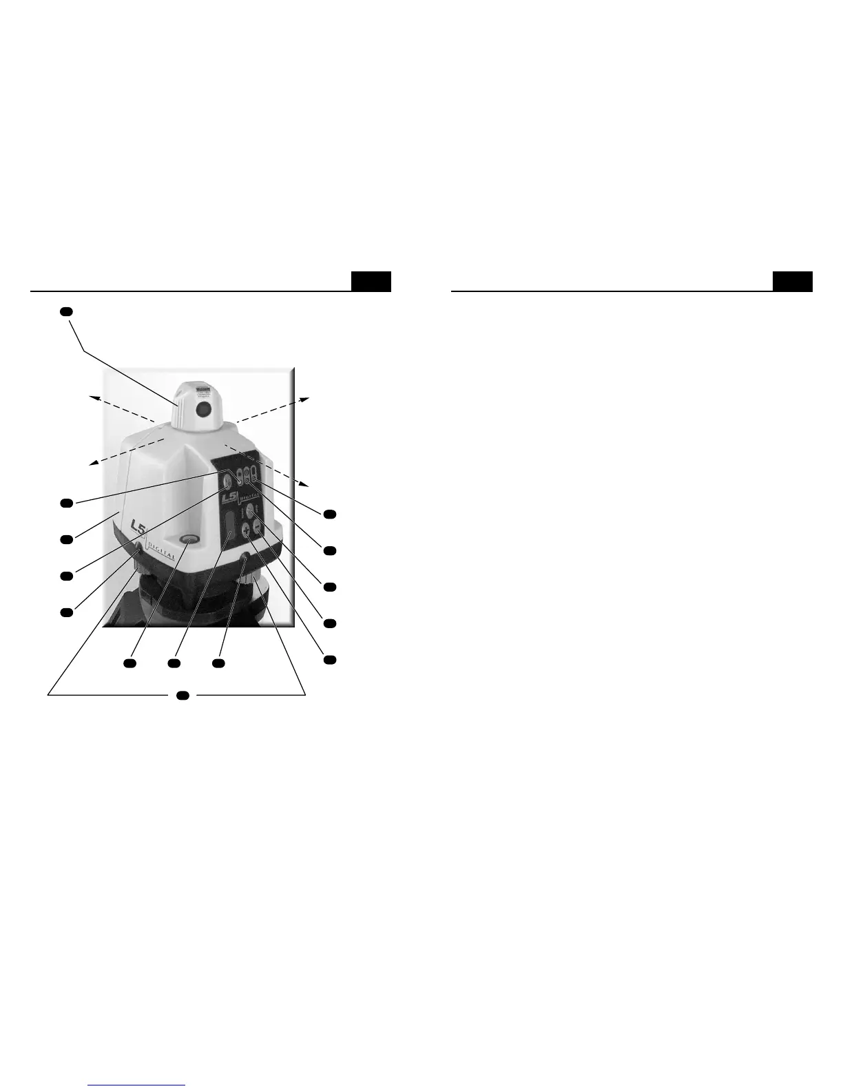
Controls And Displays
2
see note below
note: The leveling knobs are at 90º to the leveling pivot point, which is directly below the
circular vial. As you face the control panel and look down at the circular vial, the leveling
knob on your right controls bubble movement from left to right. The leveling knob at the
back (below the battery door) controls bubble movement from front to back. Turning the
leveling knob on your right in a clockwise motion will move the bubble to the right and
turning the back leveling knob in a clockwise motion will move the bubble to the back.
Turning either knob counter-clockwise will have the opposite effect.
6
4
5
9
10
11
13
2
7
1
12
3
8
15
14
-Y axis
+X axis
+Y axis
-X axis
Turn the rotating head by hand to aim the laser beam or scan
sweep. Once you have aimed the rotating head, there may
be a 2-3 second delay before the beam begins scanning.
 Loading...