CAUTION: CONTACT WITH OVERHEAD
ELECTRICAL WIRES COULD BE FATAL, EXERCISE
EXTREME CAUTION WHEN RAISING THE MAST,
LAUNCHING & SAILING.
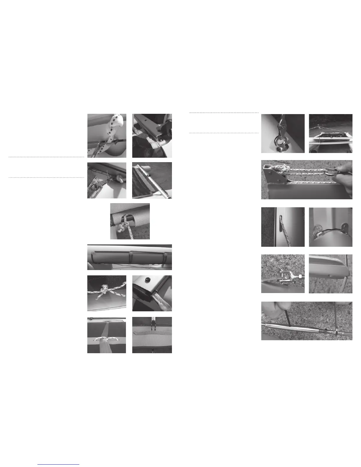
7. Rigging & Raising
e Mast
1. Position the blunt face of the striker bar
facing forward and attach the forestay striker
bar to the respective hull chain plates using
the clevis pins and rings provided. ( e gen-
naker pole retaining ring should appear on the
port side as shown).
(fi gure 16a & 16b)
2. Knot the main halyard with a short bowline
on the rear axel at the mast head. Pass the
halyard through the mainsail shackle, then
over the mast head sheave, down through
the mast groove and out through the slit on
the mast side and make a stopper knot. is
produces a 2:1 purchase system for the main
halyard.
(fi gure 17a) (fi gure 17b)
3. Attach the spreaders onto the mast as shown
(Apex of center reinforcing ridge pointing
towards the head of the mast).
(fi gure 18)
4. Attach the diamond wires to the dead end
fi xing terminals riveted on the mast side
walls. (You may have to temporarily bend the
fi xing terminals away from the mast slightly
to achieve this.)
(fi gure 19)
5. Locate the diamond wires in the grooves in
the outboard end of the spreaders. e
diamond wire should be secured to the
spreader with rigging wire.
(fi gure 20)
6. Tighten the diamond wires to ensure they
are “tight” or 150 kg measured with a loose
gauge. (Measured at half height between the
spreaders and the lower bottle screws).
7. To tighten the diamond wires you will need
a 2 mm allen key to turn the barrel of the bottle
screws and a 5 or 6 mm spanner to prevent the
turning of the bottle screw unwinding the
natural weave composition of the wire. (Hold
the spanner static and rotate the bottle screw
using the allen key).
(fi gure 21)
8. Finally, check the mast is straight by
looking up the mainsail lu groove, if not
adjust diamond wires accordingly.
1. Identify the trampoline direction: halyard bag
upwards and near the main beam.
2. Remove external sail slide from the main beam
by removing the related screw.
(fi gure 6)
3. Remove one front beam end cap and insert the
trampoline into the bottom groove on the main
beam.
(fi gure 7)
Please note: To prevent damaging the trampoline on the
edge of the beam track, the trampoline should be held straight
during insertion.
• It is recommended you adjust the trampoline tension periodically.
4. Put the removed sail slide back in place and
retighten the screw.
(fi gure 8)
5. Attach the four tramp corner lines to the four
external sail slides with a bowline or stopper knot.
Lace these lines around the trampoline eyes and
sail-slides. Check to ensure the trampoline is well
centred. Tie the front corners fi rst so that you have
some slack near the front of the trampoline, then
tension the rear corners fi rmly.
(fi gure 9)
6. Take the trampoline aft line and knot it onto the
port end of the trampoline tube as shown.
(fi gure 10)
7. Tension the trampoline aft line and thread it
progressively round the plastic buttons on the aft
face of the rear beam then back around the
trampoline tube as shown.
8. Take particular attention to keep the trampoline
tube well centered and tie the trampoline aft line
back o to the trampoline tube after it is passed
round the last plastic button on the far starboard
side of the rear beam.
(fi gure 11)
9. read the toe strap tramp lines as shown so they
form toe strap guides on the upper side of the tram-
poline and grab handles on the lower side. (Used
to steady the boat when righting after capsize).
(fi gure 12)
10. Insert the toe strap sail slides into the upper
groove on the main beam on both sides.
(fi gure 13)
11. Pass the respective toe straps through the
preferred toe strap guide, then through the respec-
tive cut-outs in the skirt at the aft end of the trampo-
line.
(fi gure 14)
12. Tie the aft end of the respective toe straps o
securely to the deck clips positioned on the forward
face of the rear beam. (
fi gure 15)
13. To complete the platform assembly, double
check all hatch covers, beam end caps and beam
fi xing plugs are repositioned correctly.
6. Trampoline Fitting
fi gure 6 fi gure 7
fi gure 16bfi gure 16a
fi gure 17a
fi gure 17b fi gure 18
fi gure 19
fi gure 21
fi gure 20
fi gure 8 fi gure 9
fi gure 10
fi gure 11
fi gure 12
fi gure 14
fi gure 13
fi gure 15
 Loading...