Page 9
EC-2502
LASKOMEX PPUH, ul. D¹browskiego 249, 93-231 £ód, tel. (42) 671 88 00, fax (42) 671 88 88, e-mail: laskomex@laskomex.com.pl, http://www.laskomex.com.pl
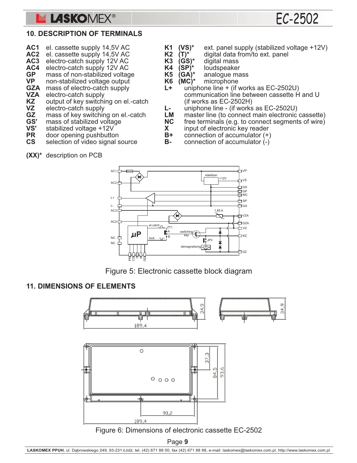
10. DESCRIPTION OF TERMINALS
AC1 el. cassette supply 14,5V AC K1 (VS)* ext. panel supply (stabilized voltage +12V)
AC2 el. cassette supply 14,5V AC K2 (T)* digital data from/to ext. panel
AC3 electro-catch supply 12V AC K3 (GS)* digital mass
AC4 electro-catch supply 12V AC K4 (SP)* loudspeaker
GP mass of non-stabilized voltage K5 (GA)* analogue mass
VP non-stabilized voltage output K6 (MC)* microphone
GZA mass of electro-catch supply L+ uniphone line + (if works as EC-2502U)
VZA electro-catch supply communication line between cassette H and U
KZ output of key switching on el.-catch (if works as EC-2502H)
VZ electro-catch supply L- uniphone line - (if works as EC-2502U)
GZ mass of key switching on el.-catch LM master line (to connect main electronic cassette)
GS' mass of stabilized voltage NC free terminals (e.g. to connect segments of wire)
VS' stabilized voltage +12V X input of electronic key reader
PR door opening pushbutton B+ connection of accumulator (+)
CS selection of video signal source B- connection of accumulator (-)
(XX)* description on PCB
Figure 5: Electronic cassette block diagram
11. DIMENSIONS OF ELEMENTS
Figure 6: Dimensions of electronic cassette EC-2502
demagnetizing
ZT1
A
B
AC1
AC2
AC3
AC4
VP
VS
GS
GP
1,85 A
VZA
GZA
GA
VZ
KZ
GZ
el.catch
lock
+12V
stabilizer
L+
L-
MC
SP
PR
CS
T
GD
X
NC
NC
JP3
switching
key
uP